OESTEX © Tube Amplifier Pages
THE
McINTOSH
MI-350 and MC-3500
HI-FIDELITY TUBE AUDIO AMPLIFIERS
For
Those Interested In Owning The World's Best Vacuum Tube Amplifier - Consider
The Extremely Excellent
McIntosh MI-350 and
MC-3500
350W rms HIGH POWER
HIGH-FIDELITY
TUBE AUDIO AMPLIFIERS - (original 1968
MC-3500 MKI design)
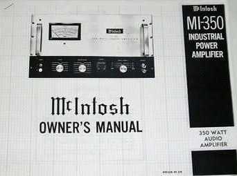
Of the numerous tube audio amplifier
designs and models produced by McIntosh since 1949, the mighty McIntosh MC-3500, or its industrial
version the McIntosh MI-350,
designed by Mile Nestorovic in about 1968, is unsurpassable - in my humble
opinion, the greatest commercial tube amp ever made.
This amp is derived from the 1949
original McIntosh unity coupled design shown above and was produced by McIntosh
between 1968 and 1971.
The MC-3500 and MI-350 offer beauty
in style and finish, functionality, reliability and performance.
A blend of art and science.
The MC-3500 and MI-350 amplifiers
were produced by McIntosh between 1968 and 1971.
This was the golden age of tube audio
- at the pinnacle of its commercial development. However the world changed very
quickly soon after with the introduction of solid state amplifiers. Their low
cost, comparable reliability and lower weight soon displaced high powered tube
amps. The result was that although the McIntosh patent was granted in 1971 its
commercial purpose was limited by evolution in a competing technology.
The combination of patent protection
and solid state power transistor developments meant commercial interest in this
technology lapsed.
Nonetheless, the MI-350 and MC-3500
stand for all time as monuments to the technological possibilities and listener
rewards of high-fidelity vacuum tube audio.
Tragically, due to competitive forces
and technological development, a comparative solid state professional quality
amplifier having identical specifications to the MC-3500/MI350 can be purchased
in 2012 for as low as one quarter of the 1971 price of the Macs. Allowing for
inflation over 40 years that is a tremendous cost reduction over time.
When the current 2022 resale value of
up to USD$10,000.00 per each - as determined by the market - is considered,
then the ratio of used MC-3500/MI-350 to brand new solid state amp is something
like 100 times. The audiophile market obviously thinks this expenditure is
justified.
However notwithstanding published
specifications, there is no comparison of sound quality. Solid state amplifiers
just do not cut it for audiophile performance and the cost of the MC-3500/MI350
is entirely justified by its performance. There is simply nothing like it on
this planet.
If you do not believe that claim then
prove it for yourself.
SPECIFICATIONS: MC-3500
ELECTRICAL:
350W RMS continuous. 500W RMS Maximum.
Frequency Response: 20-20kHz (+0
-0.5dB).
Total Harmonic Distortion:
0.15%.
Intermodulation Distortion: Unmeasureable - ie behold measuring instrument
threshold
Hum and Noise Levels: -95dB.
Output - Rated Load Impedances: 1, 4,
8, 16, 50 and 64 ohms.
Note: Rated Power Output for 1 ohm load is 300W and 4 Ohm load is 320W
Output Load Circuits: Can be isolated from ground - ie "balanced
output".
Internal impedance: less than 5% of
Rated Load Impedance.
Input impedance: 200k.
Input sensitivity 1.1V RMS
FRONT PANEL:
Anodized gold and black panel. (Note: Some after-market replacement panels were
supplied in natural aluminium anodised finish).
Input connectors: RCA and BNC (front and rear).
Gain control.
Meter Range switch: off, volts, dB, dB-10 or V1-V8.
Power circuit breaker: on or off.
Output range switch: 1 , 4, 8, 16, 50, and 64 ohms with corresponding
voltages 17.3, 35.8, 53.0, 75.0, 132 and 150V.
Dual banana output connectors.
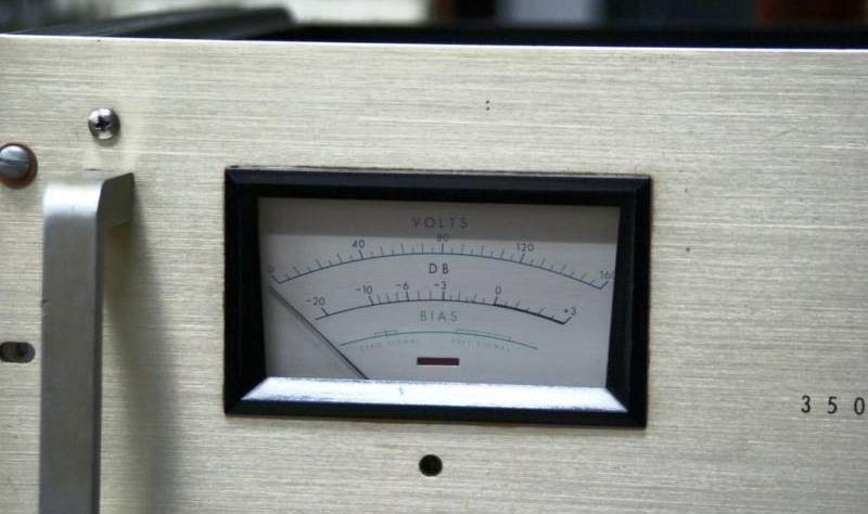
Meter: Monitors output voltage, dB or cathode current for each output tube.
Heavy duty drawer-pull style handles.
BACK PANEL:
Line voltage switch: 117 or 125V.
Output barrier strip.
Input terminals.
Sub sonic filter switch: In or out.
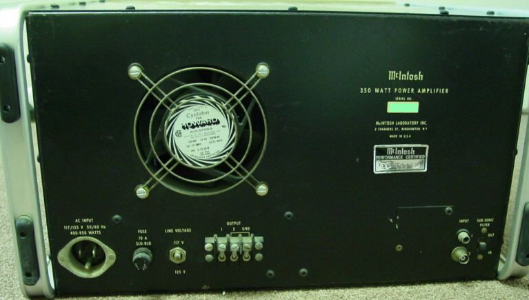
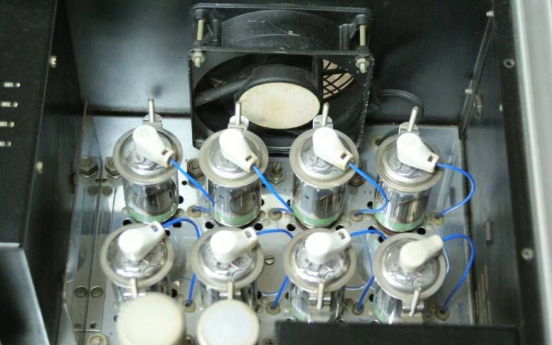
Cooling fan.
TUBES:
8-6LQ6/6JE6B output,
2-12AX7/ECC83,
2-6DJ8/ECC88,
6CG7/6FQ7
6BL7GTA.
Solid state full-wave bridge rectifier.
DIMENSIONS: 19" Wide rack
mounting x 10 1/2" High x 17" Deep behind front panel.
WEIGHT: 125 lbs
POWER CONSUMPTION:
400W at zero signal
900W at maximum signal
MANUFACTURE:
Sold from 1968-1971.
1971 retail price USD$1099.00
SPECIFICATIONS: MI-350 :
Generally as for the MC-3500 but with
the front panel anodised natural (silver) aluminium.
The MI-350 also has an optional
plug-in input transformer to support balanced input loads of 50, 250 and
600 ohms - in addition to the high-impedance inputs as per the MC-3500.
My correspondents have not been able
to identify any other significant variants, however there were some minor
changes made to the on-off switch/circuit breaker setup in the early models.
The parts lists indicate the power
and output transformers are the same in both models.
The MI-350 has a variable output
impedance selector switch knob on the front panel that enables output loads of
1 - 4 - 8 - 16 - 50 - 64 ohms. (Same as for MC-3500)
A vital element in the design of this
amplifier is the 6LQ6/6JE6B "compactron" vacuum tube. This tube has
some special features such as novar compactron construction, 30 watt plate
dissipation, 200 watt short-time plate dissipation, extra plate cooling fins
for cooler operation, 5 watts screen grid dissipation, 2.3A dark heater (the
6JE6C has a 2.5A heater).
As far as I can determine to date,
there is no practical difference between the two models.
One view is that the MI-350 was
actually produced first for the industrial, recording, public address and
specialty applications markets, then the MC-3500 produced as a later variant
for the hi-fi market. This might explain its industrial design approach and
construction quality.
At the time of its introduction to
the market there was nothing else like it.
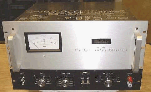
McIntosh MI-350 Amplifier - Front Panel
(Compare with the pics below)

McIntosh MC-3500 Amplifier - Front
Panel
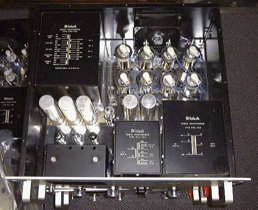
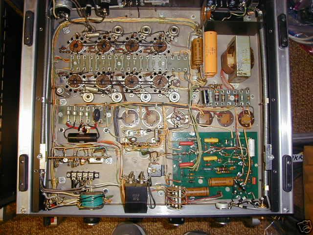
McIntosh MC-3500 Amplifier - Internal
View with Top Cover removed
Note the chassis layout re the driver stages - the driver tubes are shielded by
the electrolytic filter capacitors
The output transformer is on the left-hand side presumably to provide
right/left weight balance.
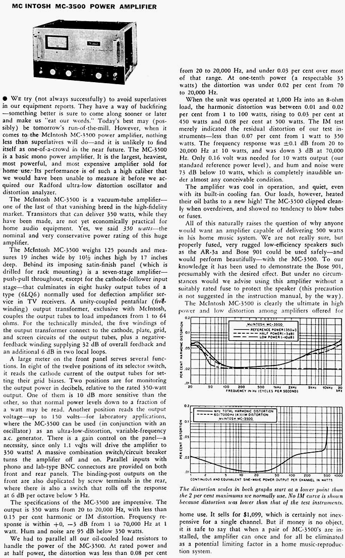
Review: Courtesy of "Stereo
Review" Magazine, November 1969 Issue
The advice regarding installing a
fuse in the loudspeaker circuit is interesting. If the fuse blew at full
output, the owner could expect to face a truly horrendous repair bill. These
days, installation of a core-balance circuit breaker into the output circuit
and controlling a contactor in the mains supply might be a smarter move.
DESIGN
The unity coupled MI-350 and MC-3500
amplifiers were designed by Mioljub R. Nestorovic in about 1968.
Given the ground-breaking electronic
circuit advances incorporated in this amplifier, together with his attention to
detail, it is likely it may have been on his mind for some time before that.
Those conceptualised thoughts
combined with market demand for high power with high quality reproduction
created a conjunction of forces that provided commercial opportunity for such a
device.
On 17 February 1969, an application
to patent the design was lodged with the US Patents Office - Application
799867.
US Patent 3573648 was granted 6 April 1971.
The patent describes the design as a
"High Power Audio Amplifier Having Feedback Provided By A Winding Co-filar
With An Output Transformer Primary Winding".
This description tells us much about
the design paradigm and together with the text of the patent suggests it was
conceptualised as an extension of the original Frank McIntosh unity coupled
design of 1953 - US Patents 2477074 and 2646467.
But Mile went further, also creating
voltage amplifier and driver stages that of themselves were unconventional
cutting edge at the time.
The Patent also refers to prior
patents of Corderman 1959, Romander 1959 and Wolcott 1963.
For a detailed explanation of how the
output stage works refer to the Patent text and drawings.
However it is important to note that
these amplifiers are much more than an electronic circuit on paper.
Great attention has been given to
component selection, component layout, chassis construction and, of course, the
transformers.
OUTPUT STAGE CONFIGURATION
Reference to the original McIntosh 1949 design shows the primary Plate and
Cathode windings are each 1000 Ohms, presenting a 4,000 Ohms Plate to Plate
load to a single pair of tubes
In addition the full Cathode winding
presents a 1000 Ohms Cathode to Cathode load impedance.
Importantly, the two secondary
windings are also each 150 Ohms, thereby providing a 600 Ohms terminal suitable
for public address line system applications. Taps at various points and
connection configurations permit loads of 4, 8, 16, 32 and 600 Ohms.
There is also a 600 Ohm tap on the
Plate primary windings for direct balanced output, bypassing the secondary.
The MI-350 and MC-3500 are a different beast
entirely
One of the key design innovations is
the splitting of the Plate and Cathode loads into two separate parallel equal
load impedance circuits combined with four parallel pairs of power tubes.
There is much discussion of the
Output Transformer design at https://www.diyaudio.com/community/threads/mcintosh-mc-3500-schematic-information.139241/
The first point to note is that four
pairs of parallel connected power tubes requires only one quarter the Plate to
Plate load as for a single pair.
This immediately reduces the number
of turns of wire needed to attain the required load by the square root of 4 =
half the turns
The five primary windings are split
into ten half sections
The above website link reports the
original MI-350 Output Transformer has an impedance of 150 Ohms per each HALF
section of the five full centre-tapped winding.
The common Plate load per side of the
B+ centre terminal is therefore 150 Ohms – 600 Ohms for the full winding pair.
Similarly the common Cathode load per
side of the centre terminal is 150 Ohms – 600 Ohms for the full winding pair.
The power output is taken from BOTH
Plate and Cathode windings, hence the total load per side on the tubes is the
sum of the two impedances. The load on each side is then the sum of 2 x
600 = 1200 Ohms.
Since there are four pairs of tubes
in parallel supplying the transformer, it follows the effective load per pair
of tubes in push-pull mode is 4800 Ohms.
The eight interleaved secondary
windings when connected together provide outputs for 2 x 1 Ohm and 2 x 4 Ohms
with a 1 Ohm tap.
This arrangement provides for loads
of 1, 4, 8, 16, 50 and 64 ohms at the output terminals
Note: The MC-3500 MKII has a single
winding secondary with taps at 4, 8 and 16 Ohms.
Importantly the actual IMPEDANCE
ratio for each (Plate and Cathode) full primary to 64 Ohms full secondary is
only 1200/64 = 18.75. The turns ratio is just 4.33:1
However EACH Plate and Cathode half
winding is only 150 Ohms so the turns ratio per primary winding section is just
2.16:1 – a remarkable achievement.
Typical push-pull output transformer
IMPEDANCE ratios are in the range 750-2500:1 with TURNS ratios in the range
27-50:1
The very low turns/impedance ratio of
the MC3500/MI350 series results in very close coupling between primary and
secondary windings that maximizes current transfer efficiency and minimises
transformer distortion.
This is further enhanced by the
unique McIntosh transformer design that enables close physical contact between
primary and secondary windings.
It follows the best result will be
achieved when the full secondary winding is used – i.e. 64 Ohm speakers when
the secondaries are connected in series .
Performance can only be described as
"awesome".
The end result is an object of beauty
and style worthy of a prominent place as the centre-piece of an audiophile tube
hi-fi system.
PICTURES
Under-chassis:
Rear View:
Top:
Underneath:
Cooling Fan:
Meter:
UPGRADING
In the mid to late 60's when this
amplifier was designed, the availability of electrolytic capacitors was limited
in capacitance range, voltage range, physical size and cost.
Modern capacitors use more advanced
materials and different construction techniques, thereby offering more grunt in
a smaller package. Compact computer bus grade capacitors offering high
capacitance values and higher operating temperatures are now readily available.
Both performance and reliability can be simultaneously improved.
Consequently the power supply can be
upgraded to deliver more energy to the output stage.
One mod that could save a bundle is
to reduce the B+ to 450 VDC, thereby allowing 450 VDCW/500 VDCPeak caps to be
installed.
This small change enables the caps to
be in parallel instead of series, thereby easily doubling (or more) the
available capacitance to the power supply circuit in the space available. The
6LQ6/6JE6B screen-grid voltage should be left as-is. The reduction in
continuous power output would be small however dynamic music performance (PMPO)
will be increased dramatically.
The only practical limit to capacitor
value is the available physical space under the chassis.
The same applies to the voltage
amplifying and driver stages, where some styles of modern coupling capacitors
offer improved sonic characteristics (to subjective personal taste of course).
Driver stages also benefit from large
filter capacitors, which prevent voltage sag during dynamic peak signals.
The 8 uF and 12 uF polarised
electrolytic capacitors coupling the output transformer windings may be
beneficially replaced with high-quality non-polarised polypropylene motor start
caps.
Also about 100 uF of non-polarised
caps installed in parallel with the main filter caps provides non-polarised
sonics to the mid-range and highs where harmonics are more audible.
Tread your own path.
MI-350 UPGRADE project by ZED AUDIO Click to view
McIntosh
MI-350 Amplifier - Front Panel
Here are details of a major upgrade and refurbishment project upon his personal pair of MI-350 high fidelity tube audio amplifiers performed by Stephen Mantz of the ZED Audio Corporation.
Click to view Stephen’s personal acccount of his Project
Note: ZED Audio report measured output power of the MI-350 MKI is 490 Watts
rms.
MI-350
Service Manual and Schematics
Roger Russell's McIntosh History
Dave O'Brien's McIntosh Amplifier Clinic
MIOLJUB (MILE) R. NESTOROVIC
The mighty MC-3500 hi-fi audio
amplifier and its industrial version the MI-350, were designed by Mile
Nestorovic (pronounced Meela Nestorovich) in about 1968 while he worked with
the McIntosh organisation.
This single contribution to the world
must be recorded as one of the great events of all time in the art and science
of audio engineering - not so much because the product excels in every respect
in its own right, but for the hidden gems of innovation and evolution buried
within its design and construction.
Design patents and copyrights at the
time ensured the world could not learn the detail of this fine work, or its
underlying design philosophies, so it has taken around 40 years for us to
unravel the finer points of his design.
My understanding from correspondents
is that the output transformers are penta-filar wound in the manner of the
original McIntosh amplifiers for maximum coupling efficiency (and therefore
transient response) and minimum leakage inductance, so are not conventional -
thereby illustrating just how excellent an amplifier can be when designers
strive for the ultimate.
Several years ago, Mile suffered a
massive stroke, which sadly did not kill him, but instead left him a prisoner
in his own body, unable to care for himself, unable to communicate save by
blinking his eyes, but cognizant of his circumstance and his surroundings.
Mile needed intensive nursing home
care during those years since, but although his family gave him all of the
support they could, love and care were not enough to change his condition.
Finally his body gave up the fight
and Mile passed to higher life on 1 May 2009.
May his memory live on through his
great technical achievements.
Vale Mile Nestorovic.
For the record, Mile was born and
educated in Yugoslavia. He was Christened "Mioljub" but he chose to
use "Mile" after emigrating to the USA.
If anyone has further relevant
information on Mile Nestorovic, please email to me at diyaudio@oestex.com
McIntosh Laboratories
released a completely new and upgraded version of the MC-3500 in November 2021.

For details see my MC-3500 MKII page. (select and click to view)
IMPORTANT COPYRIGHT NOTICE:
Copyright and intellectual property
in these audio amplifier designs and circuits remains with their original
owner.
Their inclusion in this page as
reference materiel is not a license to reproduce or use them for any purpose
contrary
to the terms of any original copyright notice or license.
These reproductions are presented for
historical information and education purposes only and are not intended for
construction.
No warranty is given of any kind as
to fitness for purpose or performance or rating.
Their source is not acknowledged here
because I am unable to determine their origin.
This page was last modified 15
December 2022
This page is located at http://www.oestex.com/tubes/mac/MC-3500.html