
OPTIMISED ELECTRON STREAM © TECHNOLOGY
for
AUDIO
and RF MODULATOR
TETRODE,
PENTODE AND BEAM POWER TUBES
This website is dedicated to the protection and preservation of tube audio technology.

OPTIMISED ELECTRON STREAM © TECHNOLOGY
for
AUDIO
and RF MODULATOR
TETRODE,
PENTODE AND BEAM POWER TUBES
This website is dedicated to the protection and preservation of tube audio technology.
This page is dedicated to the Williamson Amplifier, which is regarded by audiophiles as one of the great moments in audio history.
Its intent is to present a tribute to the contribution of Mr. D.T.N. Williamson to tube audio, and to provide information to users and DIY constructors of the features, advantages and disadvantages of this amplifier.
The information provided herein is based upon sources available to this writer. I have not been able to find any useful information on either W.T. Cocking of Wireless World or G.R.Woodville of GEC.
If any reader can offer additional information
of fill in any gaps on any aspect of this page then please
email
me.
1. D.T.N. Williamson
David Theodore Nelson Williamson was born 15 February 1923 and died 10 May 1992.
He was elected a Fellow of the Royal Society (F.R.S.) in 1968.
During the early to mid 1940's he was employed by the M-O Valve Company (the Marconi-Osram Valve Company) in England - manufacturers of "OSRAM" brand valves - as what we might now describe as an "Applications Engineer".
In 1946 he left M-O Valve Co. and joined Ferranti in Scotland, where he remained until 1960. During that period the Royal Society records his focus as being in machine tools and measurement.
However he continued interest in hi-fi and wrote a number of important articles for "Wireless World" whilst with Ferranti
Williamson continued working professionally
until his retirement in 1976, concluding his career as Group Director of
Engineering with Rank Xerox Ltd 1974-1976.
2. Introduction
A discussion of the Williamson Amplifier should be first preceded by an overview of its context in the evolution of the vacuum tube and its application to high fidelity audio reproduction.
A typical "hi-fi" triode amplifier of the time was the US made Thordason 1936 model 12 watt triode unit with transformer coupling throughout.
Transformer coupling was widely used pre-war because it was simple and effective. It was widely used throughout WWII and later - particularly for public address amplifiers and radio transmitters.
But transformers were expensive, used scarce and expensive raw materials, and performance was generally limited by the transformer characteristics to a frequency response flat from about 20-20,000 Hz at best and 100 to 5,000 Hz at worst.
Distortion was high due to the use of transformers (low quality by modern standards) and no negative feedback of any kind. Hum, noise and microphonics would have been barely tolerable.
Loudspeakers were improving at a rapid rate and their frequency response capabilities were creating listener awareness of the limitations of the amplifiers of the era.
The time had come for a great leap forward, so during the WWII years efforts were made to eliminate interstage transformers from the equation.
Details of the Williamson Amplifier were first published in the British "Wireless World" magazine in May 1947 in an article that he personally authored.
This was a time when large numbers of military personnel were being returned to civilian life and the British economy was in a state of new growth and development.
High quality FM radio and television was planned to begin and it demanded better performance than that previously tolerated as "hi-fi".
There was interest, motivation and social approval for people interested in good quality audio to think about it and, if possible, improve their pre-war equipment - by then at least seven years old and most likely much older (a long time in those days).
Pre-war valve audio obviously did not include
the significant advances made in vacuum tube technology and componentry
throughout the world during the war years, so the time was ripe for consumers
to upgrade to the benefits of that technology.
3. British Valve Manufacturing
Throughout the 1930's, British valve manufacturers had faced stiff volume and price competition from imports, sourced primarily from the USA. There was much bad blood between the British manufacturers and their US counterparts.
One strategy developed by the British Radio Valve Manufacturers Association (BVA) was to attempt to stop all imports of US made valves. This strategy included agreements with British OEM set manufacturers to use only British TYPES sourced from British factories.
Collusive wholesale, trade and retail pricing agreements between the manufacturers ensured that all valves of a similar type or class were priced identically, regardless of manufacture.
Agreements were also in place to ensure each manufacturer had access to each other's design and manufacturing technologies.
At the commencement of war in 1939, the entire British valve industry focused its resources on supplying military needs and much research and considerable development was expended in RF applications to improve frequency, power output and efficiency. This activity led to a proliferation of valve types and numbering systems.
The wartime effort resulted in a number of new manufacturers entering the valve market. Mergers and acquisitions were common throughout the war and post-war years through to the mid-fifties, as the British valve industry constantly restructured itself for survival and control of market share.
In February 1941, stocks of all valves in the UK were frozen by the Government to support the war effort.
It was realised that the industry could not defeat competition for imports if it was uncontrolled so attempts began in 1943 to standardise type numbers and rationalise the range of tube types manufactured in the UK to UK designated type numbers only.
The situation that applied during the period when Germany occupied Holland is not clear, but one assumes the people at Mullard would have happily exchanged information with their parent Philips in Holland.
In post-war 1946, production of valves in the UK was only 45% that of 1944 production - the manufacturers were hurting !! (It was not until 1950 that valve sales increased significantly over immediate post-war levels.)
This was also a time when the floodgates were opened to imports from Europe. During the period 1945-1951 most valve imports were sourced exclusively from Holland - perhaps something to do with the 100% ownership of Mullard by Philips in Holland since the 1920's. Mullard enjoyed the greatest market share.
This was precisely the time in history when Mr Williamson embarked on his research project to produce a superior audio amplifier for Britain and the MO Valve Company Ltd.
His chosen vehicle for publication of his
new design was the "Wireless World" magazine, a widely circulating publication
that covered ham radio and audio topics.
4. The MO Valve Company
The M-O Valve Company was originally established in 1919 as the Marconi-Osram Valve Co. Ltd. - "Osram" being the trade name of GEC lamps and valves - in an equal joint venture partnership between GEC and Marconi,.
In 1920 the company changed its name to the M.O. Valve Company.
This company was a minority supplier in the industry, with the Mullard group (also founded in 1919) supplying more than 40% of the pre-war market. Mullard had been WHOLLY owned by the Dutch Philips group since 1927. By 1954, Mullard had increased their market share to nearly 60%.
The M-O Valve Company was a minor, but important player.
A number of changes occured in the ownership of the Marconi portion of the parent shareholding, resulting in later changes to the brand naming of the valves - but they are complex and not described here.
In February 1952, the M.O Valve Company and Radio Corporation of America (RCA) formally agreed to the mutual use of each other's patents and exchange of manufacturing information, covering both receiving and transmitting valves.
In July 1956, the General Electric Company Ltd. of England (GEC) became the sole owner of the M-O Valve Company.
GEC also manufactured KT66 tubes under the name of "Genalex".
Unfortunately, British GEC valve manufacturing
closed its doors in the early 80's.
One of the functions of Engineers at M-O Valve Co. was to promote the use of valves (electron tubes) by designing and publishing circuit diagrammes (schematics) of radio and audio apparatus for set manufacturers and to a lesser extent, the public domain.
This was a standard industry practice of the time and reference to tube manuals and handbooks from that era and before, provides a host of "typical" circuits and applications for that manufacturer's products.
During the 1940's the art of hi-fi was evolving, with some significant breakthroughs in engineering.
The long playing microgroove recording was one such advancement, offering reduced surface noise, improved wider frequency response and dynamic range - a little like the quantum evolutionary step achieved with the compact disc. The LP record spawned a host of new pickup designs, shifting the focus of audiophiles from "crystal" pickups to magnetic.
This in turn caused the pickup manufacturers to compete and produce better and better devices, in an attempt to extract the most stored information from the record groove.
One of the "standardised" customs in tube hi-fi was to use triodes whenever good quality sound was sought.
However during WWII, which ended not long before the LP, a wide range of beam power tubes was developed for military RF applications.
Since the war ended, demand for tubes dropped off to that of more "normal" economic times, so the tube manufacturers looked to the audio market for sales.
The MO Valve company had been making a range of tubes that were "conventional" so could not offer a product that would be competitive with some of the more popular types supplied by other manufacturers.
Although the audio market had long determined that triodes sounded better than pentodes, there were few triodes available that offered superior performance, particularly when higher power was sought.
The PA market used tetrodes, pentodes and beam power tubes for the extra efficiency and power they provided.
One major advantage tetrodes, pentodes and beam power tubes had over triodes was the use of indirectly heated cathodes instead of filaments. This feature simplified power supplies and eliminated hum in the output stage. For reasons that remain a mystery to this writer, tube manufacturers across the globe did not produce an indirectly heated triode for the domestic market - ie radio and TV receivers and audio equipment etc.
One reason might be that for the small incremental cost of an extra grid winding in the valve to produce a beam power tube, a significantly more efficient performance could be obtained with no discernable reduction in sound quality to the domestic customer.
As demand for power output increased, tube manufacturers turned to their RF tube catalogue for ideas.
By "mix and match" methods they were able to make available domestic versions of military RF types, field proven during the war.
One such valve was the 30 Watt class KT66 Beam Tetrode, derived from the CV1075 "military" type.
In their monumental 1957 work "An Approach to Audio Amplifier Design", GEC Engineers W.I.Heath and D. E. Leakey, together with MO Valve Engineer G.R. Woodville said this of the KT66 valve:
"The KT66 has achieved a world-wide reputation in setting a standard of performance in its class.
Introduced in 1937, it was used in very large quantities by the military services in World War II because its efficiency and reliability and it has since become the basis of many amplifiers with output powers up to 50W.
It is widely used in domestic and industrial amplifiers connected in push-pull triode or ultra-linear circuits for outputs of high quality from 15W to about 30W.
A well known example of a push-pull triode design is the "Williamson" amplifier introduced by the M-O Valve Co. Ltd. in 1947."
(end quote)
It is significant that this group of eminent engineers did not find fault with the Williamson design and simply reproduced the "improved version" in their 1957 work along with their other somewhat more advanced designs that covered the range from 5 watts to 1100 watts.
Many of these designs were based upon the same basic circuit configuration as the Williamson, and were supported by copious technical explanation and engineering justification.
It is also significant that although the 1947 and 1949 Wireless World articles did not appear until after Williamson left MOV to join Ferranti, the above publication claims the original Williamson design as an MOV product. That would be legally correct since he was an employee, and might explain why, unlike McIntosh, Acrosound (Hafler and Keroes) and Dynaco (Keroes) in the USA, Williamson never produced the amplifier commercially under his own name.
So it is difficult in retrospect to know if the Williamson concept was his own personal invention, a team effort, an extension of corporate engineering policy or the foundation of M-O Valve Co. corporate engineering design policy.
Nonetheless, the
original design was released to the public domain by the M-O Valve Company
in 1947 so we must be grateful to them for their commitment to supporting
the design and the KT66 valve on which it is based.
5. The Wireless World "Quality Push-pull Amplifier"
The story of the Williamson amplifier must begin with the Wireless World "Quality Push-Pull Amplifier" Project, that commenced in 1934 and concluded in 1946 under the guidance of W.T.Cocking.
Cocking was a guru in valve electronics and wrote several authoritative texts on radio and television subjects.
The Wireless World "Quality Push-Pull Amplifier" Project was a progressive but evolutionary project, building on technologies developed throughout the 1920's and 1930's, then extending into WWII technological advancement spinoffs.
The "Quality Push-Pull Amplifier" amplifier was modified from time to time to take advantage of new British valve types as they became available and the increased power output delivered from them.
Each step in its evolution was based upon sound, proven design principles and supported by extensive testing.
All of Mr. Cocking's claims made were independently verifiable.
The designs were conservative, well received by the readers and remained popular.
Interestingly, the Wireless World "Quality Push-Pull Amplifier" project does not appear to have suffered when Britain was deeply involved in a war (WWII 1939-1945) other than a limitation of tube types available to the public.
Curiously, in the July and August 1944 editions, Wireless World published an article entitled "Aesthetics of Sound Reproduction" by H.A. Hartley. This was shortly after the "D Day" invasion of Normandy on 6 June 1944 and during a period when more than a million allied troops were being landed in France.
One might ask why the British public was permitted to pursue the luxury hobby pastime of "hi-fi" when the entire nation was committed to saving itself and others from invasion - perhaps it was a useful distraction from the maiming, killing and widespread destruction.
However Wireless World continued publication throughout the war years and the "Quality Push-Pull Amplifier" project continued on and off unabated.
Scott Frankland, writing in the December 1996 edition of "Sterophile" magazine, said : "Cocking is chosen as the harbinger of high fidelity because his amplifier was to evolve into the famous Williamson."
The full text of Scott Frankland's article is set out herein for reference as Page 1, Page 3, Page 4, Page 5, Page 6, Page 7
For reasons not yet known to this writer, D.T.N. Williamson appears to have taken over the amplifier project from W.T. Cocking in 1947, and Williamson's design was first published in the April and May 1947 issues.
Not to be outdone by Cocking, and to draw a line in the sand for those who might dare to follow, Williamson wrote the immortal words - "Theamplifier can be described as virtually perfect for sound reproducing channels of the highest fidelity. It provides an ideal amplifier for sound-recording purposes, where "distortionless" amplification and low noise level are of prime importance."
He also declared:- "The considerations underlying the design of a high-quality amplifier were discussed in the first part of this article" - thereby obliquely dismissing Cocking's (and others) previous efforts with the stroke of a pen.
To add weight to Williamson's claims, the August 1949 edition of Wireless World proudly declared:-
"In the Australian Radiotronics (Nov/Dec 1947) it was described as "by far the best we have ever tested ..........It not only gives extraordinary linearity and lack of harmonic and intermodulation distortion, but is comparatively simple............"
However the truth is that issue No. 128 (Nov/Dec 1947) of the Australian "Radiotronics" Magazine, published by the Amalgamated Wireless Valve Co (AWV) in Australia and edited by none other than F. Langford-Smith of "Radiotron Designers' Handbook" fame, carried an entirely new amplifier design entitled the AWA A515.
This amplifier was designed by highly esteemed Australian engineers F. Langford-Smith and R.H.Aston, as an improved variant of the Williamson circuit but using type 807 valves, which were being made locally in Australia by AWV for the military during WWII and thus readily available.
The Australian made 807 was widely used by AWA in public address amplifiers during the 1940's and early 1950's until replaced by the KT66 in later models from about 1954, and proved to be a very reliable and low-cost valve.
AWV was Australia's major valve manufacturer with technological manufacturing licence agreements with RCA, Marconi and Telefunken, but never made KT66's, preferring to import them from time to time from M-O Valve Co. UK., so it was natural they would turn to a valve of current manufacture from their own plant. After all, like the M-O Valve Co., they wanted to sell valves too !!
Thus the amplifier referred to in the Wireless World article was not the same amplifier as that designed and tested by AWV in Australia.
It varies in a number of design aspects and cannot be considered identical to the Williamson - it is at best "generally similar".
Details are provided below in the section headed "AWA - Type A515 Amplifier".
Then in December 1950, the Williamson design was published in the US magazine "Radio and Television News".
For another perspective on Cocking's role, refer to the article by Peter Lankshear, as published in his 1992 "Electronics Australia" booklet, "Discovering Vintage Radio"
Page 1, Page
2, Page 3, Page
4
Of particular interest is the AWA A503 push-pull triode Amplifier - similar to but conceptually different to Cocking's "Quality Amplifier" - but using US designed and Australian made 2A3 valves. The design of this amplifier was produced in August 1939.
Australia was there all along from the beginning.
* *
* * * *
* * * *
* * * *
* * * *
* * * *
* * * *
* * * *
* *
Nonetheless, notwithstanding his declaration of "virtual perfection", like its predecessor Cocking's "Quality Amplifier", Williamson's amplifier design was also modified over the years to bigger and better performance, starting with the "New Version" published in the August 1949 Wireless World issue and culminating in his and Peter Walker's 1952 Wireless World belated article reiterating its superiority over other options.
It could also be reasonably said that the 1950 Hafler and Keroes of the USA upgrading to their ultra-linear output stage configuration was yet another stage in the evolution of this remarkable project. US Patent 2680218, granted 1 June 1954, covered their ultra-linear transformer design. Then on 7 June 1955 they were granted US Patent 2710312, covering the 43% turns ration for optimum U/L performance.
Also in 1955, FM broadcasting began in the UK, opening up new horizons for the domestic hi-fi market, however most of the FM valves were imported from Germany because the British industry did not have suitable types for that technology. Again M-O Valve looked to the hi-fi audio market for sales of its locally made valves.
Then on 7 May 1957, Acrosound was granted US Patent 2791646 covering an improved ultra-linear configuration whereby the screen grid windings were separate to the plate windings, thereby enabling the application of different plate and screen DC voltages - a useful feature for high power applications.
The 1955 Acrosound USA Transformer Catalogue offered no less than three variants of the original Williamson - 12 watt triode or 25 watt ultra-linear with (interchangeable) KT66 or 807 valves, and a 50 watt ultra-linear version with 6550 valves delivering 50 watts output. It also offered a 100 watt ultra-linear amplifier having the latest transformer design using 6146 valves with separate plate and screen supplies - one serious piece of valve audio amplifier !!
Acrosound said - "Williamson amplifiers are no longer rare or novel, but their popularity remains undiminished because they offer excellent quality and were one of the first truly high fidelity circuits available to the home constructor." The triode Williamson .......has been a source of pleasure to many high-fidelity fans and music lovers. It provides about 12 watts of clean output, wide frequency response and a flat power curve."
Details of Acrosound designs are outlined in the "Acrosound" Section below. They do differ in detail to the original Williamson.
Then in 1957, the GEC/M-O Valve Company in its high-class publication "An Approach to Audio Frequency Amplifier Design", claimed the Williamson designed amplifier as its own, whilst also offering improved performance versions having the ultra-linear configuration.
The authors of this publication, GEC Engineers W.I.Heath and D. E. Leakey, together with MO Valve Engineer G.R. Woodville, like their predecessors Cocking and Williamson, supported the designs offered with extensive technical explanation and guidance.
Thus by 1957 the Williamson triode amplifier had run its course as "THE" benchmark amplifier and was being challenged by bigger and better equipment that had evolved with the advent of ultra-linear designs and improved componentry.
The KT88 had been introduced in 1957 by M-O Valve Co and its substantially higher power in either triode or ultra-linear modes ensured the lesser powered Williamson KT66 was to be displaced in the competitive world of audio hi-fi.
However, the Williamson amplifier has earned its place in history as one of the great milestones in audio amplifier design.
Modified to accommodate fixed-bias, a modern solid-state power supply with full-wave bridge rectifier, adequate filter capacitors (250 uF or more per piece) and superior M2 or M6 output transformer core steel, this amplifier in either triode or ultra-linear mode will still compete as one of the finest sounding amplifiers ever produced.
A relatively minor and easy modification for improvement is to incorporate the AWV A515 amplifier driver stages design into the original Williamson.
Those interested in developing the amplifier
even further might review the options detailed in my OESTEX
OPTIMISED ELECTRON STREAM ©
web page.
6. The KT66 Valve
The KT66 was made by the M-O Valve Company as part of its catalogue of Osram "KT" "Kinkless Tetrode" valves.
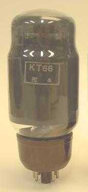
The pic above shows the original "smoked glass" version produced as a "top of the range" product, however later versions were produced in clear glass with no internal coating.
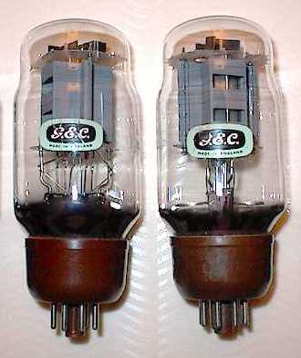
These simple box shaped plate electrode structures demonstrate different approaches to plate design by GEC, but are similar to the US made type 837 pentode (also of 1939 vintage). They stand in sharp contrast to the British ITT/STC curved plate structures demonstrated throughout their entire range (also seen in some US type 6V6 series and partly in the 6L6 series and variants).
The KT66 Beam Tetrode is equivalent to the CV1075 "common" military type.
Now it just so happens that despite some variation in ratings, CV1075 military service equivalents are the US made 6L6G and the Philips/Mullard EL37 - competitors from foreign lands.
However to this day the Osram KT66 looks the part and is ideal to grace the fashion statement of a modern audio amplifier.
Its most important attribute for audio however is its unusually high Screen Grid (G2) DC voltage rating, that matches the rated plate voltage.
It also offers a heavy duty electrode structure, often favoured for reliable service in PA public address amplifiers of the 1950's.
The original Osram ratings were Plate voltage 500 VDC and Screen Grid 400 VDC, but this was later upgraded by GEC to 500/500 VDC, thereby providing a valve that offered an ideal candidate for triode or ultra-linear connection.
Neither the 20 Watt class 6L6G (360/270) or 25 watt class EL37 (400/400) can match these ratings. Both of these types used the ST16 bottle, which looks unattractive and "old fashioned" in comparison to the KT66, which stands tall and proud to this day.
Few valves offer these attributes.
The more powerful M-O/GEC 32W KT77, 40 Watt class KT88 and 50 Watt class KT90 (EI manufacture) offer similar application characteristics to the KT66.
The KT66 is classed as a "Kinkless Tetrode"
- hence the "KT" prefix.
6.1 Why The KT66 Valve?
Now the first question to be asked is "why the KT66"?
The answer to that is relatively easy to explain.
Back in the early years of WWII the only valves available to the British public via domestic radio receivers, public address equipment and audio amplifiers were either directly heated triodes (ie with filaments and not heaters), or a small range of pentodes and beam power tubes.
At the time, it was considered that an output of about 15 to 20 watts rms was required to support good fidelity ( ie an adequate dynamic range) with available "hi-fi" loudspeakers. However there were few valves in the "receiving valve" class capable of such service.
Williamson referred to three optional valve
types in his article.
6.2 Option 1: PX25 Triode
The first was the Osram PX25 (later to become the PX25A) - a directly heated triode.
This was unsuitable for the purpose because of problems associated with hum from the directly heated filament - complicated by the use of cathode bias to the output valves. A DC power supply to the filament was out of the question because of cost.
Not only that but the PX25 cost 1/3 more per piece than the KT66
Finally, the PX25/PX25A had a 4 volt 2 A filament - requiring an extra power transformer winding to the 6.3V front-end valves.
There were other triodes in the M-O Valve
Co. stable but these were expensive transmitting valves and would not have
been suited to the domestic market where price is critical. They also required
much higher drive voltages, again beyond the realm of domestic applications.
6.3 Option 2: 807 Beam Power Tube
The second choice was the US made 807 transmitting valve, widely used in military equipment during WWII.
The 807 was made by STC Brimar UK as the 807 in an ST16 bottle and was released in August 1945.
The UK equivalents by STC are 5B/250A and 5B/254M in a tubular bottle but the manufacturing period is not certain. They were produced as "special" valves for rugged electro-mechanical applications and would have been out of the question for domestic hi-fi use.
These three types are included in the 1959 Brimar Valve Manual No.8 complete with application circuits.
It was also made by Mullard in an ST16 bottle as the QV05-25 transmitting valve. (Later Philips versions were in compact bottles).
But this valve was not in the Marconi/Osram stable in the early 1940's and would have done nothing to promote their business. Brimar and Mullard were competitors so there was no point in helping them.
The STC Brimar Tube Data Sheets refer to its propensity for parasitic oscillations, not helped by the plate top cap and consequent long and exposed plate leads.
Top cap valves are not ideally suited top domestic equipment because of the risk of electrocution from careless users.
It had an ST16 bottle so looked "old fashioned".
This valve was also a US import at a time when the British valve industry was struggling to keep imports out of the equation.
It was not listed as a normally stocked item in catalogues of the period and would have been a special import from the USA - not a formula for widespread public utilisation and protection of British industry.
Finally, its price was 50% per unit more
than the KT66
6.4 Option 3: EL37 Pentode
Another - but unmentioned by Williamson - choice was the Philips/Mullard EL37. But this valve was also a competitor's product and very likely an import.
It also had an ST16 bottle, so did not
have the modern appearance of the KT66.
6.5 Option 4: KT66 Beam Power Tube
So the only other available option to M-O Valve Company to wave the flag for England and itself was its proprietary type KT66, which had been around for some years in military applications and had a proven track record.
The KT66 looks very similar to the PX25A and cost the same as the US made 6L6G, the domestic equivalent of the 807.
One interesting point is that with the same plate and screen grid voltages as used by Williamson for triode connection, the Osram valve data at the time stated an output of 50 watts for pentode connection of KT66's - a long way from 12.5 watts in triode configuration.
The solution was to convince the public that 12.5 watts was adequate for home hi-fi.
In his 1947 original article, Williamson said:
"(6) Adequate Power Reserve.
The realistic reproduction of orchestral music in an average room requires peak power capabilities of the order of 10-15 watts when the electro-acoustic transducer is a baffle loaded moving coil loudspeaker system of normal efficiency. The use of horn-loaded loudspeakers may reduce the power requirements to the region of 10 watts."
Note the active word is "peak" watts - ie about 10 watts rms with normal loudspeakers.
Incredibly, Cocking suggested the Wireless World Quality Amplifier with its 4 watts output was also adequate !!!
One wonders how they would have felt about
modern surround sound home cinema systems having 5 x 100 watts plus a 300
watts sub-woofer in the lounge room !!!
6.6 Others
The EL34 had not yet been released and it was not until about early 1950 that it became available.
But being a competing Philips/Mullard product, GEC were not likely to want to promote it in their literature.
The KT88 was not introduced until about
1957 by the M-O Valve Company and although it was suitable for triode connected
operation the emphasis was on ultra-linear connection which offered twice
the power output for the same cost and physical sized equipment.
7. The Wireless World Quality Push-Pull Amplifier Project
Some commentators have reported that the Willamson Amplifier was the culmination and continuation of previous work undertaken for Wireless World by W.T.Cocking - commenced in 1934 and concluded in 1946 - called "The Quality Amplifier".
This proposition seems to have merit.
It is worth reviewing this project to give us a baseline for the Williamson design.
These are the Cocking designs as published in Wireless World in December 1943 - upgraded in January 1946:
a) Triode Power Valves Version
Type PX4 Valves - Power Output 8 watts
Type 6V6G Valves Triode Connected - Power Output 2 watts
Type PX25 Valves - Power Output 12 watts
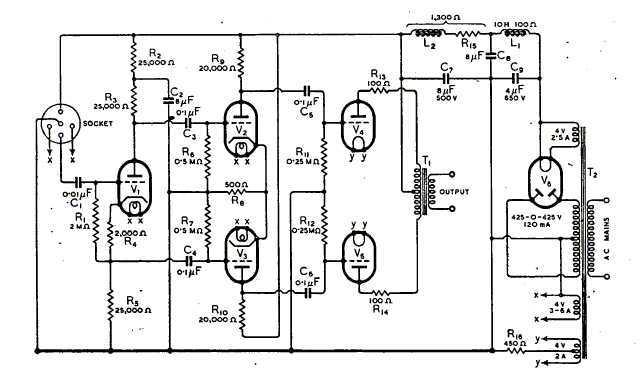
The article supporting text says: "It was found, too, that a really undistorted output of 4 watts was obtainable, and this was considered to be ample for nearly all domestic requirements."
Comparison of this amplifier with the Thordason above shows that the interstage transformers have been replaced by R/C coupling but the remainder is much the same.
T1 is replaced by the cathodyne phase-splitter and T2 is replaced by R17, R18, C5 and C6.
The use of cathode bias in the Cocking design (R16) maintains the balanced drive output stage.
However the Cocking amplifier is significantly
less costly to manufacture and significantly lighter in weight than the
transformer coupled designs it replaced.
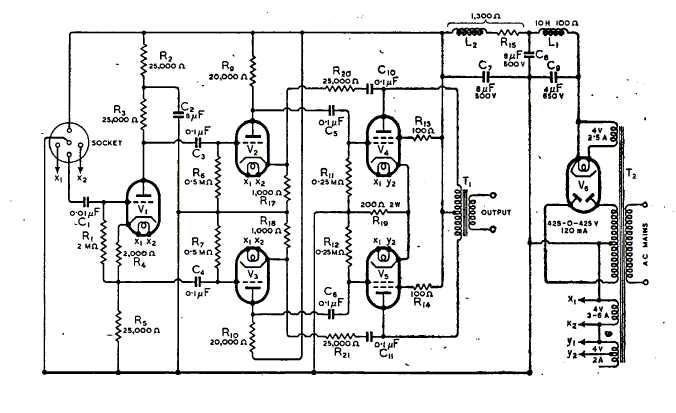
b) Beam Power Tube Output Valves Version
Type 6V6G valves - Power Output 6 Watts
8. The Williamson Amplifier
The design of this amplifier was first presented to MO Valve Company management in 1944 as "Internal Report No. Q253".
Allowing at least a year for its circuit development, output transformer design and manufacture, chassis construction and wiring, testing, modification and finalisation, it is reasonable to assume the project would have been commenced as early as 1943.
Thus it had been on the corporate books for some years before release for public publication.
As noted above, the supply of valves to the British public had been frozen by the Government back in 1941, so publication of the design of the amplifier back in 1944 would not have been smart business strategy.
What is curious is why the company's time and resources were allocated to this project in the middle of a war. Perhaps it was a natural domestic audio spinoff from a military project.
However in 1947 the time was right for its release to the world, in an attempt to improve the market share of MO valves.
8.1 The Original Williamson Amplifier
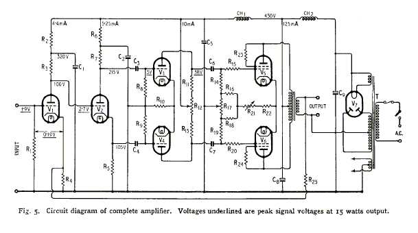
It can be readily seen the basic circuit is essentially the same as the Cocking design as shown above, excepting that voltage amplifier V1 is added to offset the loss of gain from the addition of negative loop feedback and to increase sensitivity from 2.5 V rms to 1.35 V rms. (Cocking did include a design for a separate preamplifier).
One important difference is that R1 in
the Cocking design is replaced by V1 in the Williamson - that has a profound
effect on dynamic performance as explained below.
8.2 The Improved Williamson Amplifier
The "improved" Williamson Amplifier Circuit - as revised by Williamson 1949 and re-issued by GEC 1957 - is shown hereunder.
Changes from the original design are minimal and relatively insignificant to performance.
They include the addition of C2 and R2 to improve stability in the negative loop feedback circuit and use of an indirectly heated rectifier to limit voltage surge at switch-on.
They also included construction details on a single chassis instead of a separate power supply unit.
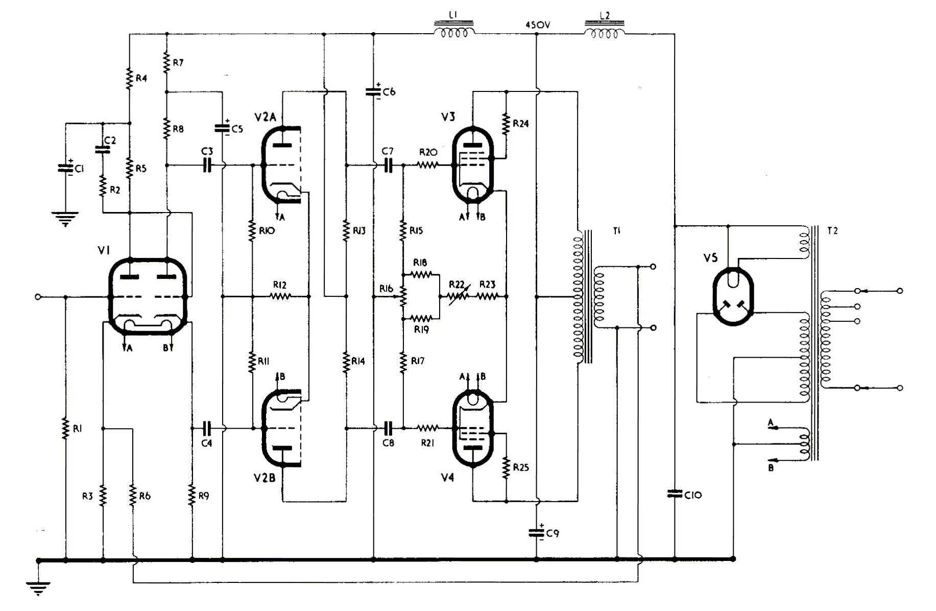
Parts List for the above amplifier:

Important Note:
Although not shown in the parts list the actual filter capacitors used were oil-filled paper types.
These offer a superior tonal quality and overall performance than simple electrolytic types and should be used where practicable. 440VAC Motor-start capacitors may also be used if preferred.
These non-polarised capacitors will have contributed significantly to the popularity of the "Williamson sound".
Historical research
indicates most commercial versions throughout the world of the Williamson
design used polarised electrolytic capacitors - most likely to reduce cost.
Despite claims of equivalent performance the reality is that they would
not have had the same tonal qualities as the original.
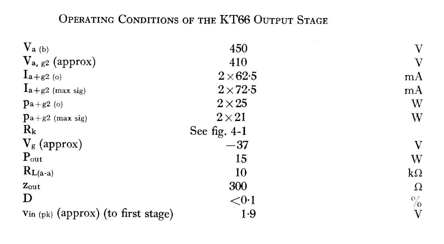
Operating Conditions for the KT66 in triode connection in the above amplifier:
Intermodulation Distortion figures are not quoted by Williamson, however the early 1950's Goodsell Model G18/C model version of the improved Williamson Amplifier was tested and the following results measured:
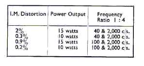
These results are not quite up to the claim by Williamson in his 1949 article:
"No distortion can be detected, even when the amplifier is reproducing organ music including pedal notes of the 20 c/s order, which reach the threshold of maximum output."
However the results are still very good - even by today's standards.
The important point to remember is that
this amplifier "sounds" hi-fi.
9. Important Design Principles
It must be said that there is absolutely nothing in the Williamson design that was new in its time - except perhaps the triode connection of a beam power tube.
Everything else was tried and true technology.
But what Williamson did was to present to the public domain through his Wireless World article, a set of guidelines and principles that had been thoroughly tested and proven by research, development and testing.
However amazing the performance on paper of this amplifier its success ultimately relied upon the quality of the design and construction of the output transformer.
Fortunately the British Partridge Company were able to build a transformer to his specifications.
This transformer had no less than eighteen separate but interleaved windings - ten primaries and eight secondaries -- all brought out to a terminal board for external connection.
It was also fully hermetically sealed and potted - ie military quality - and therefore quite expensive.
However the results were well worth the cost because there was nothing available at the time - except for the much more expensive and superior US McIntosh amplifier - that would sound anywhere as pleasing to the ear.
The Williamson amplifier took the world by storm.
But as history shows, competitors were
ready to challenge and it was not long before other manufacturers were
offering alternatives.
10.
The AWA Type A-515 AMPLIFIER (Click on link
to open page)
11.
Acrosound Williamson Amplifiers - 4 models
(Click on link to open page)
12.
Dynaco Williamson Amplifier (Click on link
to open page)
13.
UTC Williamson Amplifier 20W (Click on link
to open page)
14.
UTC Williamson Amplifier 25W (Click on link
to open page)
15.
UTC Williamson Amplifier 35W (Click on link
to open page)
16.
UTC Williamson Amplifier 50W (Click on link
to open page)
17.
UTC Linear Standard Amplifier 20W 1956 - Williamson Upgrade
(Click on link to open page)
18.
Heath W3-AM Dual-Chassis 20W Ultra-linear Williamson Amplifier
(Click on link to open page)
19.
Heath W4-AM Single-Chassis 20W Ultra-linear Williamson Amplifier
(Click on link to open page)
20.
Heath W5-AM 25W Ultra-linear Williamson Amplifier(Click
on link to open page)
21.
Heath W6-A 70W Ultra-linear Williamson Amplifier
(Click on link to open page)
22.
Musician's Amplifier and Maestro Amplifier
(Click on link to open page)
10. FURTHER READING
For a more comprehensive account of the history of the Williamson see Peter Stinson's article at http://dalmura.com.au/projects/The Williamson Amplifier History.pdf
Further variant designs are shown at http://dalmura.com.au/projects/Williamson.php
REMEMBER - ALWAYS
TAKE CARE WHEN WORKING WITH HIGH-VOLTAGE - DEATH IS PERMANENT!!
Contact:
Dennis Grimwood
Email: contact
This page is located at http://www.oestex.com/tubes/williamson.html
This page last modified 14 February 2016