electron's

OPTIMISED ELECTRON STREAM © TECHNOLOGY
for
AUDIO
and RF MODULATOR
TETRODE,
PENTODE AND BEAM POWER TUBES
This website is dedicated to the protection and preservation of tube audio technology.
THE
AWA
TYPE A-515
WILLIAMSON
AMPLIFIER
This page presents the "AWA - Type A515 Amplifier" - a modified and improved version of the original 1947 Williamson.
It
is very similar to the “improved” 1949 GEC version of the Williamson amplifier
but uses different valves and components and a two stage PII filter for the
rectifier.
Announced in Issue No. 128 (Nov/Dec 1947) of "Radiotronics" Magazine, published by the Amalgamated Wireless Valve Co. Ltd, Sydney, Australia.


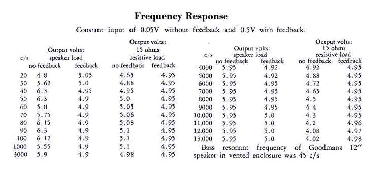
Notice how well the amplifier performs extremely well on a speaker load with no feedback.
Notice how - even with no feedback - the amplifier does not respond to the bass resonant frequency of the loudspeaker.
This is one of the reasons why it sounds so good to the ear.
These attributes may be attributed to the triode connected output stage and is typical of any power triode output valve system.
One important variant from the original Williamson is the power supply filter cap configuration. Photographs of the 1947 Williamson show oil-filled paper caps for the B+ supply. The A515 circuit shows normal electrolytic caps and it is assumed the test results were obtained with those installed.
However for best tonal results the modern constructor would be wise to use either oil-filled paper or 440VAC polypropylene motor start capacitors having as high a capacitance value as is practicable – but not more than 40 uF effective per stage of the filter.
To my ears polypropylene
motor start capacitors deliver a cleaner sound – but to each his own.
A second
important variant is the use of a two-stage PII choke input to filter rectifier
with two equal value filter chokes in the circuit. The benefit of this is
better quality DC thus better quality audio.
The A515 design
was based on the original Williamson and established before the 1949 second “improved”
version of the Williamson.
If a valve rectifier is to be used an indirectly heated valve is gentler on the filter caps. Note that with choke input to filter the capacitors MUST have a peak voltage rating equal to the transformer rms input (secondary HT) voltage x 1.414 - in this case as above that is not less than 800 VDC (hence the series connected capacitors). Although the steady state DC output will be more like 0.9 x the transformer half-wave input voltage, the initial peak voltage occurs when there is no load at switch-on, progressively reducing as the rectifier heats up and conducts.
A third important variant is the addition of a third filter choke between the output valves and the driver stage. This is a vital modification that improves linearity and dynamic response considerably because there is negligible voltage drop under load to the phase-splitter and voltage amplifier stages (as would occur with resistive decoupling).
As with the Williamson, modified to accommodate fixed-bias, a modern solid-state power supply with full-wave bridge rectifier, adequate filter capacitors (250 uF or more) and superior M2 or M6 output transformer core steel, this amplifier in either triode or ultra-linear mode will still compete as one of the finest sounding amplifiers ever produced.
Larger image of the A-515 circuit diagramme.
The image below constrained to 790 pixels width to fit on the page.
To print - first select the image and open in a new window and set print properties scale to page width.

This page is
located at http://www.oestex.com/tubes/A515.html
This page last modified 22 June 2010