oestex.com©

DISTRIBUTED LOAD
HIGH-FIDELITY VACUUM TUBE
AUDIO AMPLIFIERS
*
*
*
ULTRA-LINEAR OPERATION, also known as DISTRIBUTED LOAD
OPERATION, is a term when applied to single-ended or push-pull
vacuum tube audio amplifiers, that describes the particular output stage
configuration whereby the Screen Grids (Grid 2) of Tetrodes, Pentodes or Beam
Power Tubes are fed from a tapping in the output transformer (single-ended) or
each half of the primary of the output transformer (push-pull) - typically 43%
turns or 18.5% impedance when measured from the centre-tap, instead of from a
DC supply either independent of, or common to, the anodes.
The sonic properties of the
ultra-linear output stage configuration - albeit single-ended or push-pull
design - are midway between triode and tetrode/beam power tube
"tone".
Some audio-engineers
describe the sound of triodes as "smooth, sweet, mellow, natural" and
tetrode/beam power tubes as "clean, bright, sharp, punchy".
Technically speaking, the ultra-linear configuration delivers the same power
output as for pentode operation of the same tube under the same operating
conditions and typically about twice
the power output of triode operation of the same tube under the same operating
conditions with the same applied DC voltages - but with substantially less
harmonic distortion or intermodulation distortion (see comparative performance
graph below).
The ultra-linear
configuration also offers improved overload characteristics, resulting in more effective
power output - ie what the listener actually hears at full power levels.
Output impedance is similar
to triodes, allowing minimal or zero negative loop feedback to be used.
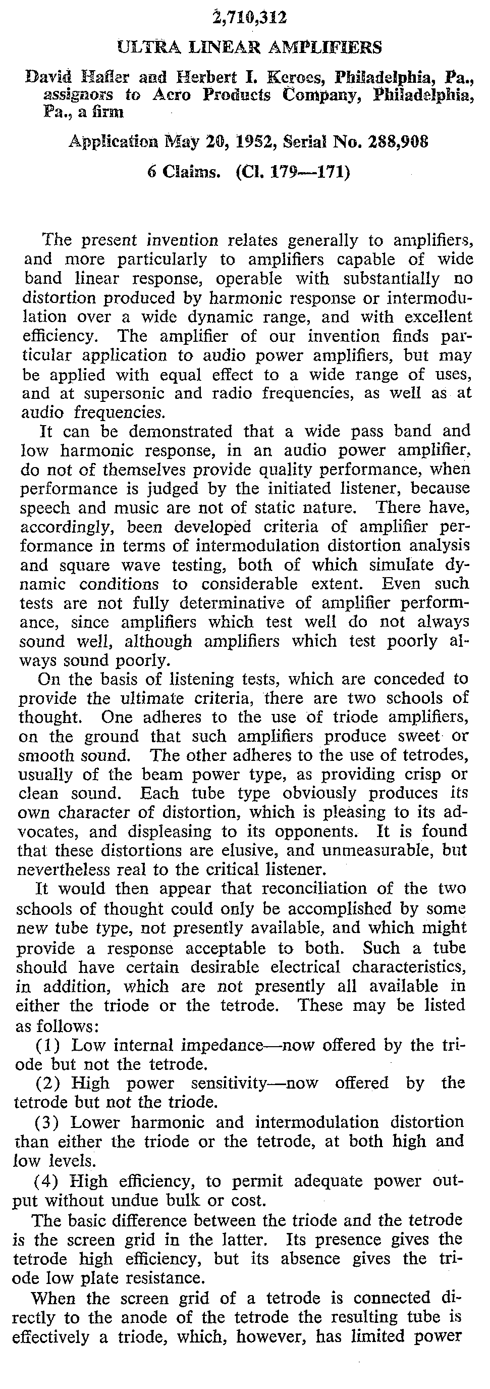
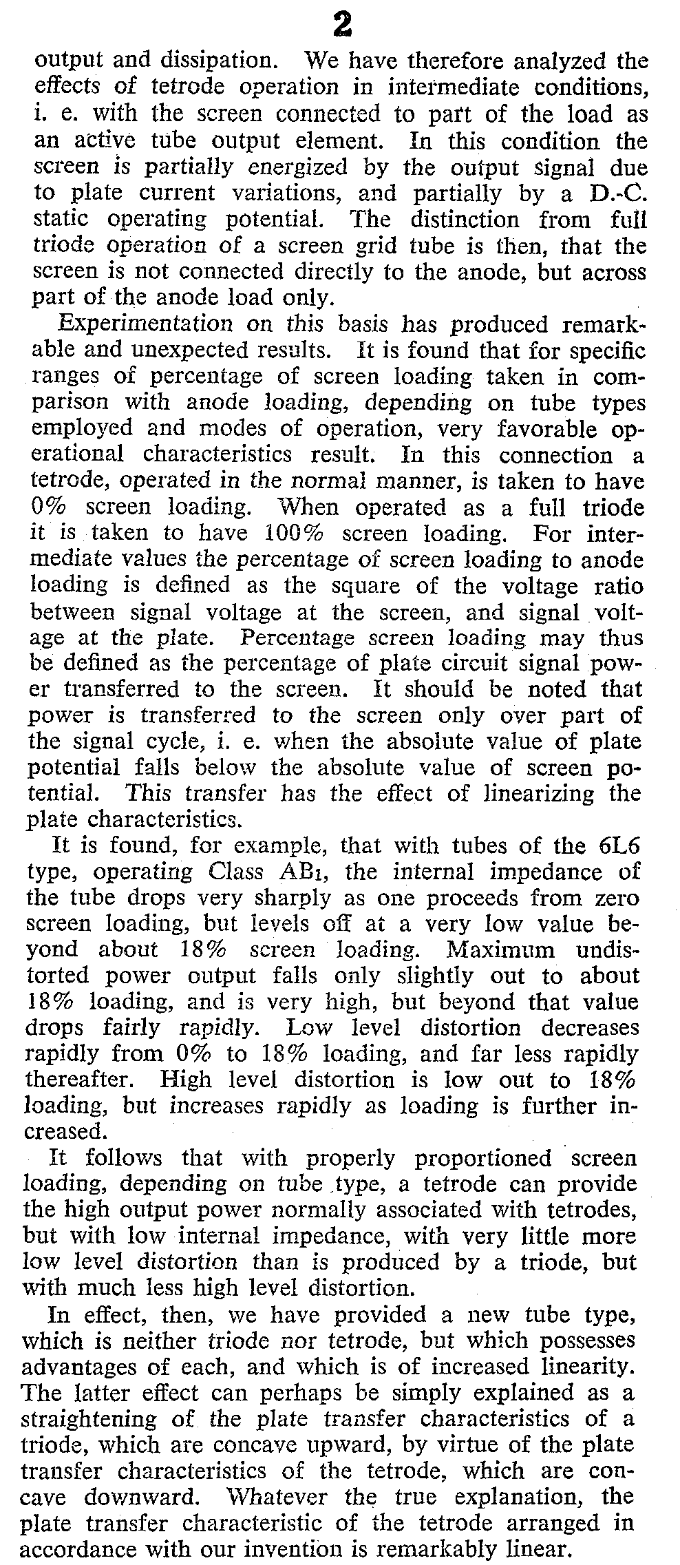
The ultra-linear amplifier
concept is beautifully described by David Hafler and Herbert Keroes in their
1952 US Patent Application 2710312.
The following extract is
included for convenience:
.
.
.
Three years later in 1955, after granting of US Patent 2710312, and supported
by further research, verification and validation, Hafler and Keroes published a
comprehensive booklet to promote their Acrosound product range of ultra-linear
amplifiers and transformers.
This rare booklet has been
made available to us from the private library of Dr. Andre G. Routh, who has
generously provided a copy for our study.
To view click here: "Theory
and Operation of the Ultra-Linear Circuit"
Note the theoretical
analysis for determining screen tap position as expounded in pages 15-17. The
"Radiotronics" papers are also referenced and linked below in this
web page.
.
.
.
The following illustrations show the conventional Ultra-Linear configuration in
three typical arrangements.
The first shows the
Ultra-Linear output stage with Cathode Bias having a common bypassed Cathode
Resistor.
Superior results will be achieved by the use of a separate bypassed Cathode
Bias Resistor to each tube.

.
.
.
.
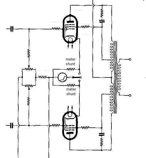
This next illustration shows Fixed Bias Ultra-Linear operation, with each power
tube having an individually adjustable bias supply for improved balance in the
output stage - essential for large power tubes:
.
.
.
.
Because the Screen-Grids are supplied with DC from taps on the output
transformer, the ultra-linear configuration therefore avoids the need for
a separate Screen-Grid supply.
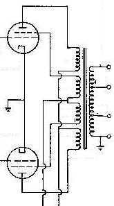
The third illustration
shows the Acrosound Ultra-Linear design, also by Hafler and Keroes,
which features a separate and lesser voltage supply to the Screen-Grids for
improved performance and cooler operation.
.
.
.
The ultra-linear output configuration is also suitable to single-ended
output stages, however only push-pull amplification is discussed in this paper.
.
.
How It All Began
One authority, F Langford
Smith of Radiotron Designers Handbook fame, attributes the original design
concept to a pair of Australia inventors, R. Lackey and R.R. Chilton of the
Australian Radio College, however the documented evidence has been lost. (If
any reader has that information please email it to me)
Consequently, in the
absence of proof of the Australian design, the ultra-linear design
concept is attributed by documented evidence to "a British subject"
Alan.D.Blumlein in 1936 - see British Patent 496,883
June 5, 1937. (Application No. 15620/37). See also expired US Patent 449,4776.
Also US Patent 2218902 (22 October 1940).
Blumlien's Patent specified
an optimum feedback tapping ratio being between 25 and 50% of plate output
voltage to the Screen Grid, however he did not use either of the terms "Ultra-Linear"
or "Distributed Load" in his Patent.
The much later detailed
work of D. Hafler and H. I. Keroes of Acro USA
(1951) demonstrated the optimum feedback voltage ratio to the Screen
Grid for a range of defined tube types.
To our benefit, they
published a paper on the topic in the November 1951 edition of "Audio
Engineering" magazine.
Specifically, the 6L6,
807and KT66 families prefer a Screen-grid load of 18.5% Plate load impedance.
(43% turns or 43% Plate Voltage).
Interestingly, they also
claim the 6V6 family prefers a Screen-grid load of 5% Plate load impedance.
(22.5% turns or 22.5% Plate Voltage).
This concept is fully
described in US Patent 2710312,
dated June 7, 1955. History shows Hafler and Keros successfully
patented in the USA a further development of the general concept that had
already been patented by Blumlein in the UK, had run most of its full term,
then expired (maybe not quite, because the H and K application was lodged May
20, 1952). Their claims included a level of impedance loading to the Screen
Grids of between 5% and 26% Plate Impedance - a much lower range to that of
Blumlien.
This ratio was later
verified by other respected designers, including GEC/MOV, GE USA and RCA
See also the thoughts of Norman Crohurst.
Of particular interest is
the Australian work of F Langford-Smith (of Radiotron Designers Handbook fame)
in 1955, which investigates the Ultra-linear concept in detail for a range of
tube types.
See AWV Radiotronics Magazine May and
July 1955
It is worth noting that the
original Blumlein Patent would have remained in force until 1953, so not much
would have - or could have - happened regarding practical implementation of
this technology in commercial products by other than Blumlien until after that
date.
However, long before
Blumlein's patent expired, he was killed in the year of 1942 in an aircraft
crash whilst testing a new British radar design. Thus we can only speculate as
to what might have been had he survived. It would be reasonably safe to assume
that hi-fi audio would have been allocated a very low priority during the years
of WWII during which Britain was struggling to survive.
Further reading on the life
and times of this remarkable man is available at http://en.wikipedia.org/wiki/Alan_Blumlein
Since the famous
"Williamson" amplifier design appeared some years after that date, it
is reasonable to assume the "ultra-linear" concept was either safely
locked away, or rejected by the gurus of the time in favour of triode mode. In
fact, Williamson not only rejected the term but openly condemned the concept
altogether - see Williamson and Walker - Wireless World
1952.
Thus the term
"Ultra-Linear" may be rightfully attributed to Hafler and Keroes - an
opinion supported by the "Radiotron Designers Handbook 4th Edition. This
is the term used in their 1955 US Patent 2710312 (Application date 20 May,
1952) and is supported in that Patent by technical justification for use of the
term.
In contrast to the above
documented evidence, some researchers claim the Ultra-Linear concept was
previously used in Australia as far back as 1933.
The question is - "How
many ways is it possible to configure a 4 electrode device in an electronic
circuit?"
Of course the answer is
that someone, somewhere, at sometime will figure it out.
The famous Williamson
triode-connected beam power tube amplifier was later modified by Hafler and
Keroes to incorporate the ultra-linear design concept. Details are
provided in their paper "Ultra-linear operation of the Williamson
Amplifier" by Hafler and Keroes, published in the June 1952 edition of
"Audio Engineering" magazine. It seems then that they had the last
word, by improving Williamson's design despite his dismissal of the concept..
Numerous examples of this particular design are now available on the internet.
The Ultra-linear
configuration in audio amplifiers is also known as "DISTRIBUTED LOAD"
operation.
It appears this term was
intoduced by Willamson and Walker of the UK, who objected to the term
"ultra-linear".
Of course this term is also
technically correct, because the taps on the output transformer primary do in
fact present a push-pull reactive load to the Screen Grids, enabling them to
contribute to useable power output. This is explained in detail in the Hafler
and Keroes Patent.
However importantly,
Mullard describe the "distributed load" configuration as a system of
negative feedback.
The term "distributed
load" was adopted by Mullard as corporate policy. Their use of this term
was published in the May and June 1955 editions of "Wireless
World" in their article "Design for a 20 Watt High Quality
Audio Amplifier".
It is interesting to note
that this design appeared from Mullard, notwithstanding Williamson's previous
condemnation of the concept.
I am unable to verify the
specific designer of the 5/20 amplifier but later credits go to Mullard
Applications Research Laboratories Engineers Mssrs R. S. Babbs, D. H. W.
Busby, P. F. Dalloso, C. Hardcastle, J. C. Latham and W. A. Ferguson. (No
mention of Williamson and Walker). It is assumed the commercial pragmatists won
the argument.
Mullard continued to use
this term through until at least the 1960's when their compendium of audio amplifier
and pre-amplifier circuits "Mullard Circuits for Audio Amplifiers"
was published as a second edition reprint in 1962.
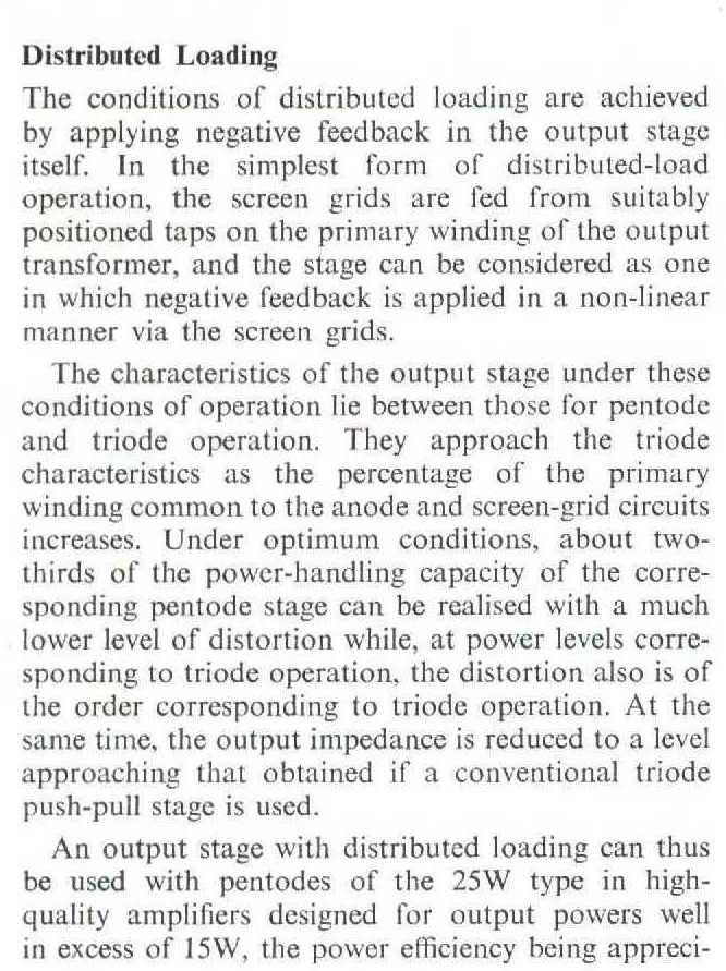
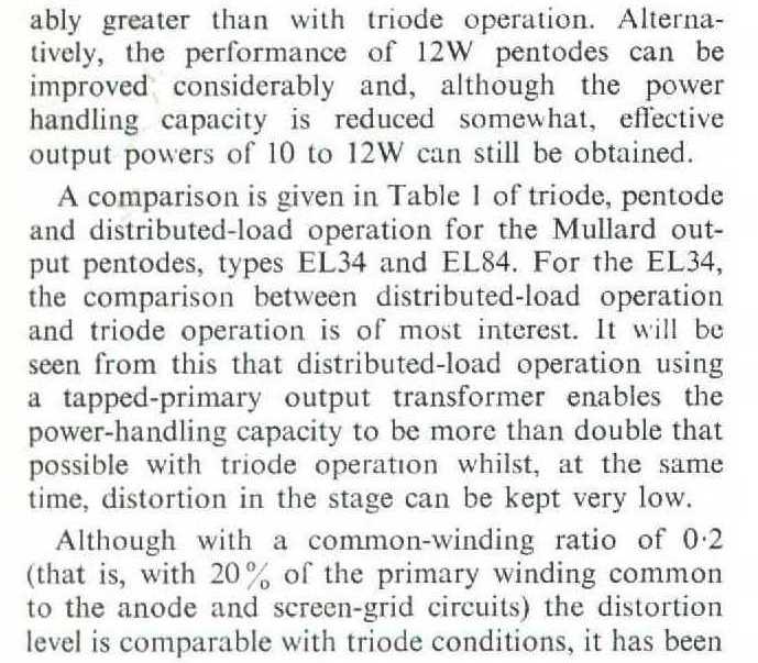
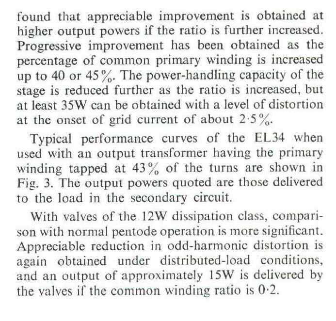
The following extract from
that publication provides an overview of Mullard's design concept.
.
For an excellent technical introduction to the ultra-linear design
concept see http://www.aikenamps.com/UL.pdf
More technical detail,
single-ended ultra-linear circuits and non-power tube ultra-linear
applications is also available from Glass Audio - "Tube CAD
Journal" Vol. 2 No. 1 - January 2000
For further views and
technical details see also http://www.vintageradio.me.uk/amplifier/10watt.htm
Important
Note: Performance described as "ultra-linear" is available only under
very specific operating conditions - and in the case of popular commonly used
audio tubes, usually where the Screen load is 18.5% impedance or 43% turns of
the Plate load impedance - measured from the power supply source (B+) terminal.
More
detailed information is provided below.
In other
cases, the term "distributed load operation" may be more appropriate.
Tube Operating
Conditions:
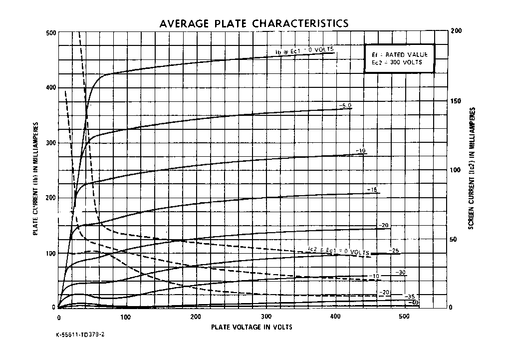
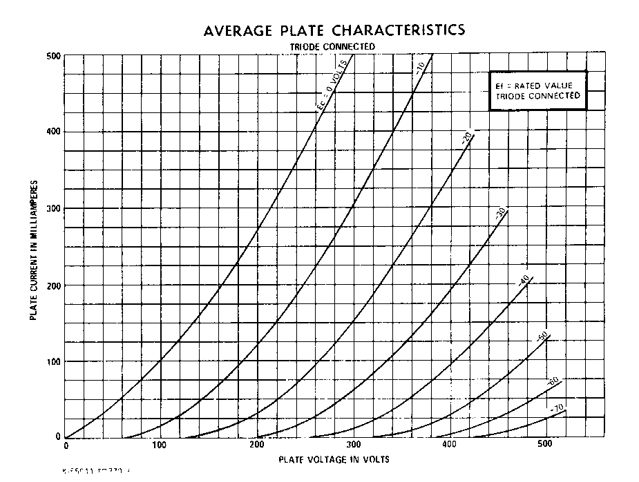
The attached graphs, courtesy
of GE USA, show the marked difference in operating conditions for pentode,
triode and ultra-linear operation of the 6550 Beam Power Tube.
6550 Beam Power Tube Operating Conditions - Pentode Connection
6550 Beam Power Tube Operating Conditions - Triode Connection

.
.
.
.
Benefits:
The ultra-linear
configuration ensures constant stage specific voltage feedback between Plate
and Screen grid in the output stage, thus reducing output impedance and
distortion, whilst improving linearity and frequency response under variably
reactive loudspeaker load conditions.
An important advantage is
that being single stage-specific, ultra-linear operation avoids the
problems of time-delay and phase-shift commonly associated with cascaded stage
amplifiers using negative feedback from the loudspeaker for the purposes of
reducing distortion and increasing loudspeaker damping.
Ultra-linear output stages provide automatic
constant ratio stage-circuit specific feedback, free from the adverse effects
of conventional multi-stage feedback systems.
Ultra-linear output stage power output is
dependent upon the proportion of Plate load that is applied to the Screen-Grids
- typically in the range 75% to 100% that of tetrode/pentode connection at the
same plate voltage - but is still twice triode connection for the same tube
type under the same operating conditions.
Ultra-linear tone or "sound"
approximates that of triodes.
Ultra-linear operation is very forgiving of
circuit design and generally provides an acceptable quality sound from average
quality output transformers. Note however that the esteemed Norman Crowhurst,
in a November 1959 "Audio" Magazine article entitled "Puzzled
About Amplifiers", indicates that a high-quality output transformer
is essential for ultra-linear operation, to ensure
high-fidelity performance over the entire audio frequency range.
To this end, Herbert Keroes
of Acrosound developed a special transformer for ultra-linear configuration
output stages. The main purpose of this transformer is to enable the use of
transmitting tubes, where the Screen-grids must operate at a significantly
reduced DC voltage to that on the Plates. Full specifications are provided in US Patent 2791646
(May 7 1957).
A set of high-fidelity
amplifier designs was published in the Acrosound Ultra-Linear Transformer
Catalogue, published a little later.
The flagship of the range -
the TO350 - offers 100W from a pair of 6146 tubes. This is an exceptional
amplifier by any standard.
Design Concept:
A good example of a typical
conventional ultra-linear circuit is shown in the GEC KT88 100W Amplifier.
A more highly developed
design is shown in the GEC KT88 400W Amplifier.
The conventional ultra-linear
configuration is arranged such that the screen grids have maximum DC voltage
applied to them (in practice slightly higher than their corresponding
plate/anode voltage because of voltage drop in the primary winding) - thus
maximising power output and efficiency, whilst simultaneously receiving an AC
negative feedback signal from the output transformer - thus minimising output
impedance and distortion.
The magnitude of the AC
feedback signal is directly proportional to the percentage turns ration of
screen tap to full winding.
The screen tap may be
positioned anywhere from 0% (pentode connection) to 100% (triode connection),
however performance and tonal qualities change relative to the ratio of the
screen tap - see GEC graph below.
In practice, research by
the inventors of this method of amplifier configuration suggests that the ideal
for most tube types is in the range 40 to 50% turns of each half primary,
measured from the primary centre tap.
Further research by Mullard
UK for the EL34/6CA7 and EL84/6BQ5, GEC/MOV Valve Co. for the KT88, GE USA for
the 6550, and RCA for the 6973 (6CZ5 hi-fi), 7027A (6L6GC), 7591, 7868 (6L6
family), also recommends 43% turns (or 43% of plate signal voltage), or 18.5%
impedance.
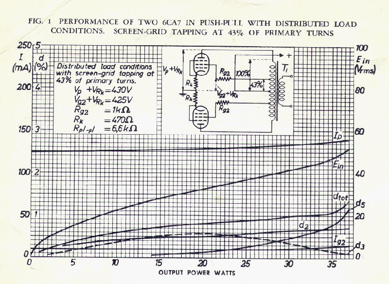
An example of EL34/6CA7
operation with cathode bias is shown in the following graph - courtesy Amperex
Electronic Corporation
.
.
.
.
Screen-Grid Operation:
One very important feature
of the ultra-linear configuration - different to normal Tetrode/Pentode
operation where both Screen-Grids are at nominal AC earth potential - is that
when one Screen-Grid in a push-pull pair is driven positive, the opposite
Screen-Grid is driven negative by the turns ratio of the output transformer
acting about the centre-tap of the transformer, which is at nominal AC earth.
This is not a problem because the opposite Plate is also being driven
negatively anyway by the action of the push-pull driver/phase splitter.
The opposite applies when the
alternating signal reverses polarity.
In Class B operation, the
output transformer operates as an auto-transformer, so the opposite Plate and
Screen-Grid are still driven to opposite polarity (together in a constant ratio
to each other), even though they are not conducting.
*
*
*
*
*
*
*
*
*
*
*
Balanced Amplifier
It should be noted that in
the case of a push-pull amplifier, the DC negative bias voltage (even if it is
at 0 VDC) applied to the Control Grid #1 is located at the centreline axis of
the balanced input signal. This means the inputs are floating and the
centre-axis is earthed. That is to say, the input Grids are being driven in a
push-pull manner about a common centre-point or axis - eg as seen with a
centre-tapped push-pull driver transformer.
Thus in a conventional
push-pull Tetrode or Pentode amplifier, any alternations of the balanced input
signal to the Control Grids will proportionately increase or decrease current
flow in both tubes of the push-pull pair in response to the input alternating
waveform shape.
Now in each tube of a
push-pull pair, the negative terminal (Cathode) of each tube is AC earthed -
even in Cathode bias.
The load on each tube is
connected between the Plate and the transformer centre-tap, so the negative
terminal of the load - which is at the output transformer centre-tap -
is also effectively AC earthed.
But most importantly to
ultra-linear operation, in a push-pull amplifier output stage, Screen-Grid
behaviour will be similar to that of Grid #1 - ie the Screen-grids will behave
as a balanced amplifier - balanced about the centre-tap of the output
transformer which, as previously noted, is effectively AC earthed - ie
variations in Screen-Grid voltage will produce proportionate variations in
electron flow in both output tubes simultaneously.
In conventional Tetrode and
Pentode operation, when the DC applied voltage to the Screen-grids is constant,
the AC voltage appearing at the balanced Screen-Grid terminals will the
product of the electron flow within each tube and will always be a voltage
determined by the natural AC voltage gradient applied internally across each
tube.
Also in a conventional
Tetrode/Pentode output stage, the AC signal voltage appearing at the
Screen-Grids is diverted to AC earth at the Screen-Grid terminals via
the filter capacitor and is lost as heat. Hence the output voltage appearing at
the Screen-Grid terminals is of no consequence to the sound produced by the
amplifier - ie it is not reproduced in the output transformer or loudspeaker.
However, in the case of the
Screen-Grids in ultra-linear push-pull amplifier configuration this is
not so, because the Screen-Grids are located at about 43% of the lineal
distance between Cathode and Plate. Thus the AC signal voltage appearing at
each Screen-Grid as a result of linear voltage gradient between the Cathode and
Plate within each tube will thereby be about 43% of the Cathode to Plate signal
voltage.
The Screen-Grids are
connected to the load so they will contribute to the sound produced by the
amplifier.
Class A and Class B
Ultra-Linear Operation
In some transmitters, it
has been the practice to drive or control the output power tube by means of the
Screen-Grid, rather than the Control Grid.
This method offers some
benefits to RF situations but is relevant to the explanation of ultra-linear
audio amplifiers.
Because the Screen-Grid is
located much further into the physical Cathode to Plate distance - ie typically
nearly centrally between them - it follows that a substantially higher AC
signal voltage must be applied to the Screen-Grid if that element is to control
the electron flow in the tube.
Operation will be the same
as for Grid #1 but at a higher AC voltage.
It follows that if the DC
Screen-Grid voltage controls electron flow within the tube and it is varied by
means of a superimposed AC voltage, then the Plate Current will vary in
response - as for conventional Grid #1 operation.
But what if the Screen-Grid
voltage is applied in 180 degrees directly opposite phase to the electron
stream within the tube - as is the case for ultra-linear operation?
Obviously the electron
stream permitted by the AC signal as applied to Grid #1 is offset by the
opposing signal voltage applied to Grid #2 via the tapping on the output
transformer - because they are both in the same circuit at the same time.
Consequently behaviour of
the tube in response to the controlling signal voltages applied to BOTH Grid #1
and Grid #2 simultaneously, will be different to that of either a Triode or
Tetrode.
This is what the above GE
graphs demonstrate - ie a change in the operating characteristics of the basic
tube, verifying the claim of Hafler and Keroes that they had produced a
"virtual" tube, intermediate between a triode and a tetrode.
The situation is however
very different between Class A and Class B operation.
In the case of Class A
ultra-linear operation, the Screen-Grid of one tube will be driven AC positive
but the Screen-Grid of the opposite tube will be driven to an equal, but
opposite polarity, voltage by the output transformer balanced output about the
AC earthed centre-tap. This will have the effect on the second tube of reducing
the effective Screen-Grid control voltage, thereby reducing voltage gain and
therefore power output - regardless of the shape of the input waveform to that
tube.
But also note that Grid #1
of both tubes is also controlling current in them.
Hence in Class A
ultra-linear operation, it is necessary to consider the effects upon Cathode
current in BOTH output tubes by BOTH Control Grids and BOTH Screen-Grids.
However in the case of
Class B ultra-linear operation, although the second tube will be similarly
driven to reduce its gain, there is no signal in it at that moment in time
because its Control Grid #1 is at cutoff bias during the relevant half-cycle of
signal input so zero or near zero current is flowing in that tube.
Thus a Class A ultra-linear
amplifier will have completely different behaviour to a Class B ultra-linear
amplifier.
Distributed Load
Operation
On the other hand, that
portion of the output transformer primary winding between the Screen-Grid
tapping and the centre-tap is not subject to cancelling out by out of phase
signal in the power circuit.
This portion of the winding
- usually 18-19% Plate to Plate load impedance - therefore imposes a load
directly onto the Screen-Grids.
Thus a portion of the power
output is delivered through this Screen to Screen winding.
However, although the
winding and its corresponding load impedance is presented to the Screen-Grids,
they are incapable of delivering much power because the Screen-Grids will be
aligned in the electron stream such that the small diameter grid wires are not
directly in the electron stream - so because of space-charge effects cannot
attract electrons.
Furthermore, the
Screen-Grids are charged to opposite polarity to the electron stream during
half of each signal alternation cycle, which further detracts from their
electron collecting capability.
For the record, in their US
Patent 2,710,312 Hafler and Keroes state: "It should be noted that
power is transferred to the Screen only over part of the signal cycle, i.e.
when the absolute value of Plate potential falls below the absolute value of
Screen potential. This transfer has the effect of linearizing the Plate
characteristics."
Power Output
Ultra-linear operation typically (for the
popular audio tube types) delivers 100% power output compared with the same
tubes in tetrode or pentode connection at the same plate voltage and bias
system (GEC) - but sometimes less for other tube types.
For example, Mullard quote
the power output for the EL34 tube as being the same for pentode and
ultra-linear connection with 20% turns screen-taps, but for minimum distortion
the screen-taps increase to 43% turns, which provides a power reduction of 15%
(but distortion is halved).
Note:
Worthy of note is the KT88, which GEC (MO Valve Co./Genalex) claim produces the
same power in ultra-linear connection as in Pentode connection at 43%
turns. This may be due to the applied Screen-Grid voltage used in ultra-linear
operation being twice the recommended value as that for Tetrode operation.
Importantly, the electrode structure of the original GEC-MOV KT88 is internally
physically identical to the GEC TT21 and TT22 RF transmitting beam power tubes,
so the GEC-MOV made KT88 is therefore capable of operating at its rated 600 VDC
maximum Screen-Grid DC operating voltage continuously without distress.
The TT21 or TT22, which
have a top anode cap and intended for professional broadcast use, may be used
in lieu of the KT88 as a direct electrical substitute. Grid to plate
capacitance is reduced, which should produce superior audio performance over
the KT88.
One of the challenges to
the home constructor is that manufacturers' tube manuals and data sheets often
quote "typical operation" for fixed bias pentode connection but
cathode-bias for ultra-linear connection.
Ultra-linear Circuit
Characteristics:
The following graph,
courtesy of GEC and AWV Radiotronics Magazine (May 1959), shows the
comparative characteristics of the KT88 in triode, pentode and ultra-linear
connections. These comparative relationships between the different connection
configurations should be typical for most (but not all) tetrodes,
pentodes and beam power tubes.
.
Note:
- the
relationship between output impedance and ratio of screen tap turns.
- the
relationship between output power and ratio of screen taps.
- the
relationship between THD distortion and ratio of screen taps.
- the
effect of load impedance upon output power.
- the
power output for ultra-linear operation is greater than that for pentode
or triode operation.
This graph shows that for ultra-linear operation the
original GEC/MOV KT88 is unsurpassed!!
- Although
having identical general specifications the 6550 Beam Power Tube - its USA
cousin, has substantially lower electrical ratings for
pentode, triode and ultra-linear connections - so be warned!!
- Although
the 6550 and KT88 are often specified in tube handbooks and amplifier
schematics as equivalent substitutes for each other it may be wise to
check the ratings first before making a change from KT88 to 6550.
- Physically,
some brands of 6550 tubes have a parallel glass envelope smaller in
diameter than the KT88 so there may be inadequate space to instal the KT88
or to provide adequate natural air cooling without major modification. The
reverse change is electrically not a problem.
- Although
the KT88 is derived from the TT21 and TT22 transmitting tube stable, the
origin of the 6550 is not clear.
- Some
users have reported detailed examination of certain Russian made KT88 and
6550 tubes suggests they are physically identical but branded for use as
either KT88 or 6550 thus it is wise to check the manufacturer's
specifications before installation in any high voltage circuit.
WARNING:
- The
GEC/MOV KT88 octal socket centre base spiggot is made from a brittle
plastic moulding material and tends to break off if the tube is not
inserted and removed very carefully from its socket. This tube is big and
heavy in relation to its octal base so is unsuited to horizontal or
inverted mounting unless retained by a suitable device.
- The
GEC/MOV KT88 was typically made with one or two base pins omitted
(presumably to save on cost) that has the effect of increasing stress on
the remaining pins whilst providing a less secure installation.
- Do
not use the KT88 in inverted mounting without a retaining device.
EL34/6CA7 Ultra-linear Circuit Characteristics:
The following graph by
Mullard UK shows performance of the EL34/6CA7 valve.
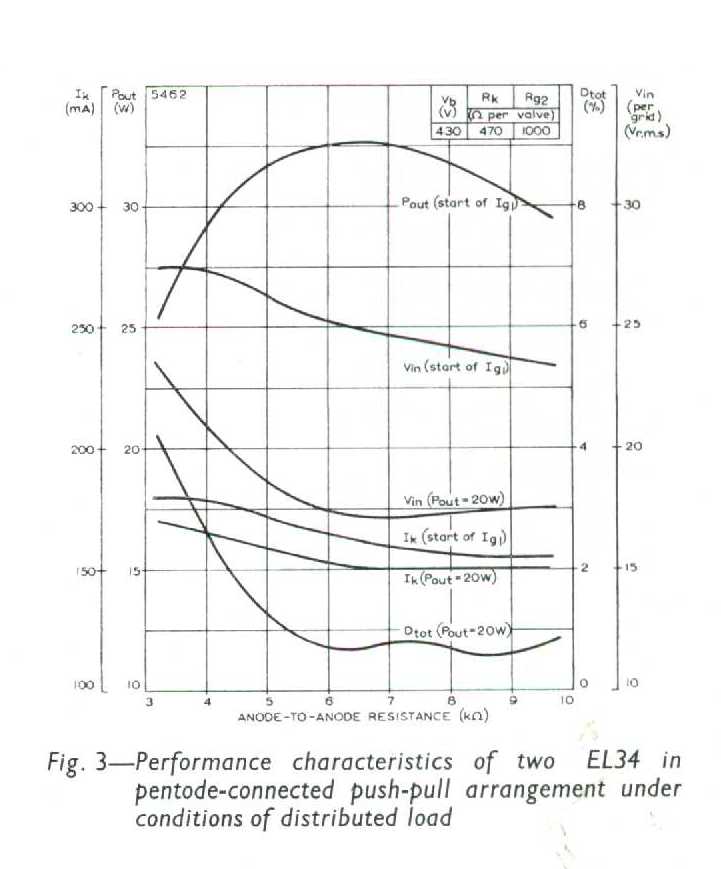
Note the comparative
"linear" performance for power out v distortion over a wide range of
loads and similar operating conditions.
Further information is
provided by the following table ex Mullard UK, that shows comparative
performance between the Mullard EL34 and EL84 valves in various output stage
configurations.

I am indebted to
Rudolf Moers, a distinguished Electrical and Electronics Engineer located
in the Netherlands, who has made available for us his recent extensive
scientific investigation into the design theory and practice of Ultra-linear
audio amplification.
These papers were added in
February 2014 with kind permission from Linear Audio http://www.linearaudio.net
and their author Rudolf Moers.
Part 1 - Power Point presentation
Rudolf Moers has published
a new book offering refreshingly different guidance for the DIY designer,
blending solid theory with practical application and a new detailed approach to
ultra-linear amplifier design.
Fundamental Amplifier Techniques With Electron Tubes - Second Edition – Rudolph Moers
2018.
Application of Ultra-linear tube audio amplification:
In practice, for tube types
other than KT88, the real loss of useable output power from the ultra-linear
connection is actually significantly less than any power differential measured
with resistive loads might suggest (i.e. a 1.5 db reduction in loudness
produced by the loudspeaker), because the ultra-linear connection
produces a higher coupling efficiency between the amplifier and loudspeaker
than tetrodes or pentodes - ie is more triode like - thus approximating an
equivalent "loudness" to pentode connection.
This phenomenom is
particularly true of low frequency reproduction, suggesting that ultra-linear
connection is superior for double bass violin, bass guitar and general
hi-fidelity reproduction down to about 40 Hz - which is the lowest musical
frequency normally reproduced in popular music.
The 6L6 family of tubes can
be used for ultra-linear connection, but only safely and reliably at
reduced voltages not exceeding rated screen-grid voltage. More suitable 6L6
style types include 5881 and 7027A - see manufacturers' data sheets for typical
circuit values.
Ultra-linear operation typically delivers about
two to three times the power output compared with the same tubes in triode
connection at the same plate voltage.
Most importantly,
inter-modulation distortion is substantially lower with ultra-linear connection
compared with pentode or triode connection for the same tubes.
Note: In the case of hi-fi
systems, percussive instruments such as the bass drum, tympany, harpsicord,
guitar and the piano present typically short-duration/transient low fundamental
frequency signals rich in harmonics. Thus they are less demanding to reproduce
than the electronic organ, pipe organ or bass guitar, which produce an
essentially long-duration signal, approximate to a sine wave, in the lower
register.
Triode connection is still
the preferred option for seriously loud organ music because of the lower
frequencies to be reproduced, the need for "boom" free bass around
the loudspeaker resonant frequency and, most importantly, a need for consistent
gain (flat response) throughout the musical scale to ensure all notes are reproduced
with equal loudness when they are recorded that way. However triodes deliver
substantially higher intermodulation distortion than ultra-linear operation so
adequate power headroom is essential to ensure clear mid to upper range
reproduction simultaneously with sustained lower register signals.
A major advantage of ultra-linear
connection over tetrodes and pentodes is the improvement in tone for recorded
music and public address reproduction. The tone is more triode like, being
smooth and mellow (but "clearer" than triodes), compared with the
harsh tone of tetrodes and muddy tone (read "less definition") of
pentodes.
Guitar Amplifiers:
Ultra-linear operation is not usually suitable
for lead guitar amplifiers because it lacks the "crispness",
"harshness" or "bite" in the sound commonly provided by
beam power tetrodes and pentodes, however some jazz and country music
guitarists may find it preferable where a smooth, natural mellow tone is
sought.
However, ultra-linear
operation is superior to tetrode/pentode connection for bass guitar
applications because low frequency power delivered to the loudspeaker is
substantially greater - ie it is "louder" - due to lower output
impedance and improved coupling to the loudspeaker.
It also has a
"deeper" tone, suggesting improved sub-harmonic performance.
Summary:
In summary, ultra-linear
connection offers:
- useable
power output approaching that of tetrodes and pentodes but with
substantially reduced harmonic and intermodulation distortion and improved
tonal characteristics, thus making it the preferred configuration for high-fidelity
applications.
- a
"warmth" of tone, not evident with the "clinically
clean" sound of unity coupling, where the load is distributed
between plate and cathode.
- simplicity
in circuit design and construction
- elimination
of need for a separate power supply to the screen-grids
- employment
of a simple output transformer
- constant-voltage
negative feedback
- high
stability operation over a range of reactive and capacitive loads
- strong
useable low-frequency power output - ie as heard through the loudspeaker
- good
dynamic range performance and transient response
Ultra-linear
operation also enables lower quality loudspeakers to be used for satisfactory
results.
Note that in high power
applications - ie more than 100W RMS, transmitting TRIODE tubes such as
805, 809, 810, 811, 812, 833, 845, 8000, 8005, etc may be a more economical and
practical solution than trying ultra-linear configuration with
tetrodes/pentodes because of simplified wiring, output transformer and power
supply requirements.
TUBES
FOR ULTRA-LINEAR OPERATION
The "Ultra-linear"
configuration avoids the conventional conflict between plate and screen
voltages by creating a voltage divider network through the output transformer
primary to AC earth (transformer centre-tap), ensuring the screen voltage
tracks and thus always remains, both below and proportional to the plate signal
voltage. By this configuration, the screen is intended to be prevented from
exceeding its power dissipation rating.
This statement is
subject to the Screen Grid always being operated within its Rated DC
Screen Grid voltage and at a DC voltage less than that of the Plate.
Applied plate (B+) voltage
for ultra-linear connection should never exceed Grid 2 rated voltage, so
standard ultra-linear configuration is only suited to tubes designed for
audio applications having a Grid 2 rating approximating either the plate
voltage rating (or actual applied plate voltage if less than rated maximum).
Important:
Reference to tube data sheets will show that few output tubes have ratings
remotely matching this requirement.
Important:
The use of poor quality output transformers having a high DC resistance in the
primary windings may establish a situation whereby the actual DC Plate voltage
drop across the transformer primary winding is high, causing the DC Screen-Grid
voltage to be higher than the Plate at high signal levels.
Unfortunately, only a small
number of tube types are thereby suitable for ultra-linear operation,
because in ultra-linear mode the screen grid is operating at or above
the plate voltage - a dangerous operating region for any tube.
Only a few tube types were
recommended by their manufacturers as being suitable for ultra-linear
connection, the most notable being EL34/6CA7, EL84/6BQ5, KT88, 6550, 7027 and
8417 - see manufacturers' data sheets for typical circuit values.
In a typical output tube,
the Screen Grid is the ANODE, or positive electrode. It is designed to
accelerate electron flow from Cathode to Plate, but is structured in such a way
that most electrons pass through it and on to the Plate for collection.
Excessive screen grid
voltage attracts excessive electrons to it, thereby resulting in excess grid
current, excessive grid power input/dissipation, overheating and melting. The
fused screen grid wires may short-circuit B+ to earth, damaging the output
transformer and/or power supply components.
Unfortunately, most audio
tetrodes, pentodes and beam power tubes are designed such that the Screen Grid
may be operated only up to a maximum DC voltage that is well below the Plate
voltage - typically 150 to 300 volts.
Plate current is very much
controlled by the Screen Grid, thus when the Screen Grid is made ineffective
(ie over-active) by application of excessive voltage, the Plate Current is
likely to exceed the tube ratings and also melt the plate.
Another way of saying this
is that if the Screen Grid voltage is excessive, the capability of Grid #1
(Control Grid) to control electron flow in the tube is diminished - or lost
altogether.
Operation of typical power
tubes (having a screen grid voltage rating substantially lower than the rated
plate voltage) in ultra-linear connection is likely to result in loss of
control over electron flow by the screen, resulting in thermal runaway or
dynatron action - resulting in self-destruction of the tube. Fire is a constant
risk.
For example, tubes designed
for RF power service typically have a plate voltage rating many times higher
than their corresponding screen grid voltage rating. This class of tube
(eg 807, 2E26, 6146, 4CX series) has the screen grid physically positioned
close to the control grid (Grid 1) and tend to self-oscillate or suffer thermal
runaway when the screen grid voltage is higher than their rated
screen-grid voltage, which is always the case with conventional ultra-linear
service, thus rendering them unsuitable for ultra-linear service.
WARNING: When using tubes fitted with a
plate top cap (anode cap) in ultra-linear configuration, consider also
the risk of self-oscillation and/or parasitic oscillations from the combination
of long leads from the plate top caps and screen grids to the output
transformer - particulary significant when using multiple tubes to obtain
higher power. Some of this lead length may be avoided by chassis layout however
in the case of top cap style tubes the screen connection is always under the
chassis, thus ultimately requiring connection in some way from top to bottom of
the tube through the output transformer.
High Power Ouput:
Where more power is needed
it is preferable to use a larger tube that is known to be more suited for ultra-linear
circuitry, such as the KT88, KT90 or 813.
Another useful option is to
run multiple pairs of tubes in parallel push-pull, such as the arrangement used
in the GEC 400W KT88 Amplifier. It goes
without saying that normal precautions against instability and parasitic
oscillations are essential in layout, lead dress, use of grid stopper resistors
wired directly to the pins, and keeping inputs away from outputs. The output
transformer must be of high quality with low leakage capacitance and low
leakage inductance between windings. Tubes should be mounted close together to
minimise inter-connecting lead length. Grid #1 circuit resistance must be held
within the manufacturer's ratings. A low-impedance driver, such as a cathode-follower or transformer is recommended.
For high power applications
where high plate voltages are needed, success may be achieved by adding a separate
winding for each screen grid to the output transformer, to enable the
screens to be AC coupled to the plates thus providing ultra-linear operation,
but separated from the DC plate supply, thus enabling the screens to be
supplied within their rated voltage from an independent supply.
The ACROSOUND 100W Ultra-Linear Amplifier using
6146 tubes and the TO-350 Transformer is an example of this excellent and
innovative design configuration.
One of the benefits of this
configuration is that the Screen-Grid supply can be independent to the Plate
supply and therefore better regulation can be incorporated into the Screen Grid
circuit. Noting the Screen-Grid is the ANODE in a Tetrode or Pentode tube, a regulated
supply will deliver improved transient response and a
"brilliance" to the reproduction not available with a common B+ power
supply as is the case in conventional Ultra-Linear operation.
Bruce DePalma,
one of the few Gurus of modern hi-fi amplifier design, presents an interesting
and comprehensive commentary on the core design philosophies supporting this
approach in his excellent Design Paper - "Analog Audio Power
Amplifier Design"
Bruce has developed designs
that enable both Ultra-Linear and low Screen-Grid voltage technologies to be
successfully integrated in such a way that extremely hi-fi performance results.
BIAS
Grid 1 bias for ultra-linear
operation is normally higher than that for tetrode/pentode connection, so
output stage sensitivity is reduced. Higher output voltage from driver stages
is therefore needed.
Grid-stopper resistors to
Grid #1 and Grid #2 are still required for ultra-linear operation.
Important: The technique of
using a silicon rectifier diode on each Screen Grid in series with the
Grid-stopper resistor, as described in my "OPTIMISED
ULTRA-LINEAR ©" page, is very helpful in ultra-linear
connection. AC signal output voltage from the Screen-Grids is prevented from
conducting through to the output transformer, which means that theultra-linearoutput
stage operates as a negative feedback system only - ie Plate voltage is fed
back to the Screen Grids via the transformer taps but not the other way around.
This method ensures all the electron flow goes to the Plates, with all the
advantages described previously.
Note:
This configuration has opposite polarity as when zener diodes are installed to
reduce screen-grid voltage, so therefore the benefits described are not
relevant to the zener diode technique.
Important - When using a
high B+ voltage:
To ensure Plate Dissipation
remains within manufacturer's rating at both zero and maximum signal, it may be
essential to use Class B operation - thus introducing further complexity into
the circuit design and perhaps offsetting much of the benefit offered from the ultra-linear
configuration. It may be more prudent to use a tube having a higher rating.
RECOMMENDED TUBES
The following tubes are
known to be suitable for conventional ultra-linear operation having nominally
equal Plate and Screen-grid DC supply volts:
TUBE
TYPE MAX.
ULTRA-LINEAR CONNECTION PLATE TO CATHODE VOLTS
6AQ5A 285
6BM8
300
6BQ5/EL84
300
6BW6
285
6CA7
500
6CM5/PL36 250
6CZ5
285
6L6GB
270
6L6GC
400
6V6GT
285
5881
400
6146A, B, W
etc
250 (Top cap style)
6550
450 (Note: GE USA
"design maximum" rating. Some brands may not tolerate this voltage)
6973
300
7027A
450
7189A
400
7581
450
7591
400 (50% turns
recommended by RCA)
7868
400 (50% turns
recommended by RCA)
807/5B-255M
300 (Top cap style)
8417
500
EL34
425
EL84/6BQ5 300
KT66
400
8417
500
KT88 600
(Note: GEC UK "design maximum" rating. Some brands may not tolerate
this voltage)
KT90
600 ("Absolute Maximum" rating)
KT94
600 ("Absolute Maximum" rating)
KT100 600
("Absolute Maximum" rating)
KT120 600
813
1100 (This tube is an excellent option for serious audiophiles but
has a top cap and requires a centre-tapped 10 V AC/DC filament supply - 5A per
tube. External wiring must be screened to prevent RF induction and parasitic
oscillations. Adequate ventilation is essential)
In my humble opinion, the
most suitable candidates for ultra-linear connection are:
6CM5/PL36
(250 VDC)
6AQ5/6V6GT (275 VDC)
6CZ5/6973 (285
VDC)
5881/6L6GC/7027A/7591/7868 (400 VDC)
KT88/KT90/KT94/KT100/KT120 (600 VDC) (may need to reduce to
450/500 VDC with non GEC manufacture)
813
(1100
VDC)
All are well proven fine
quality beam power tubes - each famous in its own right.
Other options are the EL34 (425 VDC) or 6CA7 (500 VDC) or EL84/6BQ5 (300
VDC) pentodes, however in my opinion
sound from these tubes is not as clean as those above. All of this family of
tubes "sounds" similar because of their generally identical electrode
construction.
If you have had successful
experiences with other tube types that are useful for ultra-linear connection
please email your comments.
For further information
regarding Ultra-linear operation of vacuum tubes see my OPTIMISED ULTRA-LINEAR © OPERATION page
© NOTICE:
INTELLECTUAL PROPERTY COPYRIGHT © D.R.GRIMWOOD 2002
- ALL RIGHTS RESERVED.
This page last modified 07
February 2021
This page is located at
http://www.oestex.com/tubes/ul.htm
