electron's
OPTIMISED
ELECTRON STREAM © TECHNOLOGY
for
AUDIO
and RF MODULATOR
TRIODE,
TETRODE, PENTODE AND BEAM POWER TUBES
This website is dedicated
to the protection and preservation of tube audio technology.
Home
Page
CONSTRUCTION
AND WIRING OF
TUBE
AMPLIFIERS
This page presents examples of fastidious
design, layout, wiring and construction in tube amplifiers.
There are many, many such examples available
in the world and here is but a small selection to ponder upon.
If you have one to display please send
me a link or details to the HOME PAGE email address set out below
First - "the rules":
CHASSIS AND COMPONENT LAYOUT
AND WIRING
Review of past design practice shows us that many designers had no idea
of the principles essential to optimising chassis layout.
In a wide range amplifier, the wiring and componentry act as antennae,
to pick up stray and induced signals, such as ultra-sonics, RF, hum and
noise, from adjacent circuitry and transformers.
The basic rules for component layout and wiring are:
-
do not mount electrolytic capacitors close to tubes - the caps will dry
out and fail
-
do not mount electrolytic capacitors close to transformers - the caps may
induce hum and interference into the B+ bus
-
do not mount hot tubes near transformer windings - the windings will burn
or dry out
-
do not mount driver stage tubes near transformers or mains wiring - to
avoid induced interference or hum
-
do not mount exposed driver tubes near output tubes or rectifier tubes
- they may pick up induced signals such as RF, hum and even audio, and
trigger parasitic oscillation in the circuit
-
do not mount tubes near the edge of the chassis - they can burn the enclosure
or cabinet when the chassis is installed and operating
-
do not mount input wiring near output wiring either within a stage or across
stages - to avoid stray signal induction or oscillation
-
do not mount input terminals near speaker terminals or mains supply leads
or plugs - to prevent instability and/or interference from induced signals
-
do not mount tubes upside down without restraining devices - they can fall
out partially, with loss of one or more contact pins, or completely fall
out and break
-
do not mount tubes horizontally unless their grid wires are installed in
the vertical plane - to prevent grid wire sag when hot and thus uneven
electron flow, or internal shorts
-
always use shielded wiring for signal pathways in the early stages - to
prevent stray hum and noise pickup and induced feedback signals
-
never ground potentiometer wires to the chassis at the potentiometer -
always ground directly to the relevant cathode (through a shielded co-ax
lead)
-
always shield input tubes with discrete shields or a grounded metal enclosure
(there are currently more than 100 million mobile telephones in the world,
thousands of radio and television transmitters and significant numbers
of high-powered industrial and military transmitters, and they do generate
a significant amount of RF energy for your hi-fi amp to pick-up)
-
always mount tubes as close to each other as space will permit - to minimise
wiring length and minimising exposure to induced signals or interference
(but always leave at least a 10 mm gap between bottles for natural air
cooling - more for larger tubes having more than 25 watts plate dissipation)
-
always use short leads between connection points - to minimise wiring length
and minimising exposure to induced signals or interference
-
never connect pins on tube sockets directly together with straight or solid
or heavy wire unless there is a loop to enable each socket pin to locate
properly about its tube pin - tube pins do not bend well to match socket
misalignment, so some movement in the socket terminals is essential
-
always mount tube sockets such that the heater pins are aligned with the
direction of wiring - to minimise heater lead length
-
always twist heater wires together - to neutralise AC radiation to nearby
wiring and components (cancel-out hum signals)
-
always ground grid and cathode resistors (and bypass caps where applicable)
to the cathode pin, if grounded, or to the grounded end of the cathode
resistor. One very effective technique is to instal the resistors vertically,
straight up from the socket pins, then simply join the ends to be grounded
together (neatly). Connect them via a wire to chassis ground. This bundle
of components does not need further support as they are a strong structure
mounted directly from the tube socket. Some miniature sockets have a centre
tube spiggot for shielding the pins from each other - this should be also
grounded. The tube shield provides a useful structural support
-
where practicable, instal interstage capacitors with the outer layer connected
to the previous stage plate - to minimise hum pickup Vintage caps often
had a band printed on one end to indicate the outer layer
-
try to layout the chassis following the circuit diagram (schematic) - this
method actually works!!
-
ensure the amplifier is well ventilated - to ensure adequate cooling and
to facilitate long-term component life
-
always insulate and isolate high voltage and mains power circuitry - death
is permanent!!
-
always use an isolating transformer between the mains power source and
the rectifier and heater/filament system (to prevent electrocution)
-
always insulate and isolate high voltage capacitors - particularly large
capacitance units - they can store electrical energy for several days.
An amplifier switched off may still be hazardous or even lethal
-
always use an enclosed METAL chassis system - if necessary fit a removable
lid/cover for component access. 20 gauge galvanised steel sheet (1 mm)
thick is ideal but aluminium is more suitable for large chassis to reduce
weight. Note that it is not possible to solder components to aluminium
using tin/lead solder so all chassis joints must be tightly screwed together.
-
never use 50/50 tin/lead solder - that is for plumbers. Use only a high
quality 60 tin/40 lead solder having a cored flux. When soldering components
to prevent dry joints (imperfect metallurgical joint bond) always allow
time for the joint to thoroughly heat before removing the soldering iron.
Printed circuit board conducting strip tends to separate from the bakelite/fibreglass
base board if overheated - best to avoid them.
-
always ground or earth the chassis (to prevent electrocution). Note: the
earth side (outer shielded cover) of the input shielded lead must be grounded
to the amplifier chassis to prevent hum pickup, however modern television
receivers do not have an isolating power transformer and use a "hot" chassis
system. This means that if you connect yourself - or someone else - between
the TV chassis and ground there is a high likelihood of electrocution or
death. If connecting audio signal leads to a TV receiver or similar device
ensure there is an isolating capacitor in series with each lead - ie both
live and earthed input leads, to prevent direct connection between the
amplifier and the hot (ungrounded) source. If you are not qualified to
do this then take your system to a qualified technician - you only have
one life!!
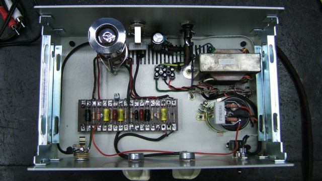
EXAMPLE 1: PN Electronics
- Australia.
Shop 3, 16 Cockburn Road, Hamilton Hill. Western Australia 6163
Website: http://www.pnelectronics.com.au/
email: info@pnelectronics.com.au
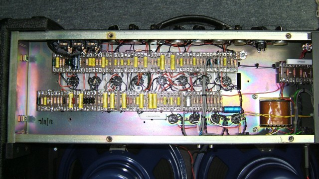
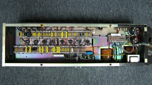
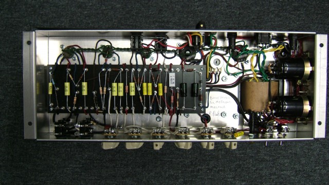
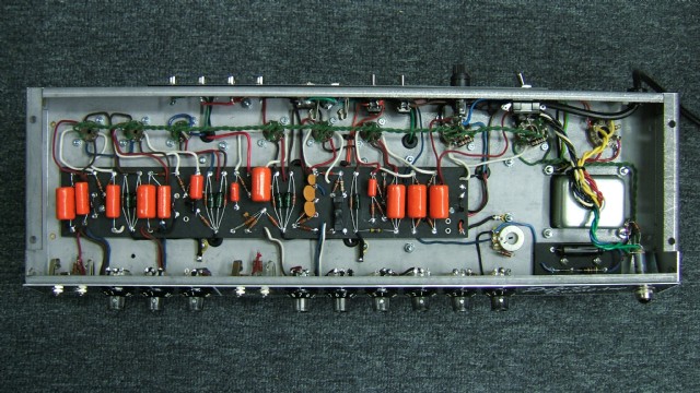
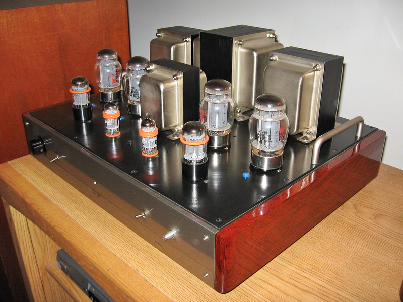
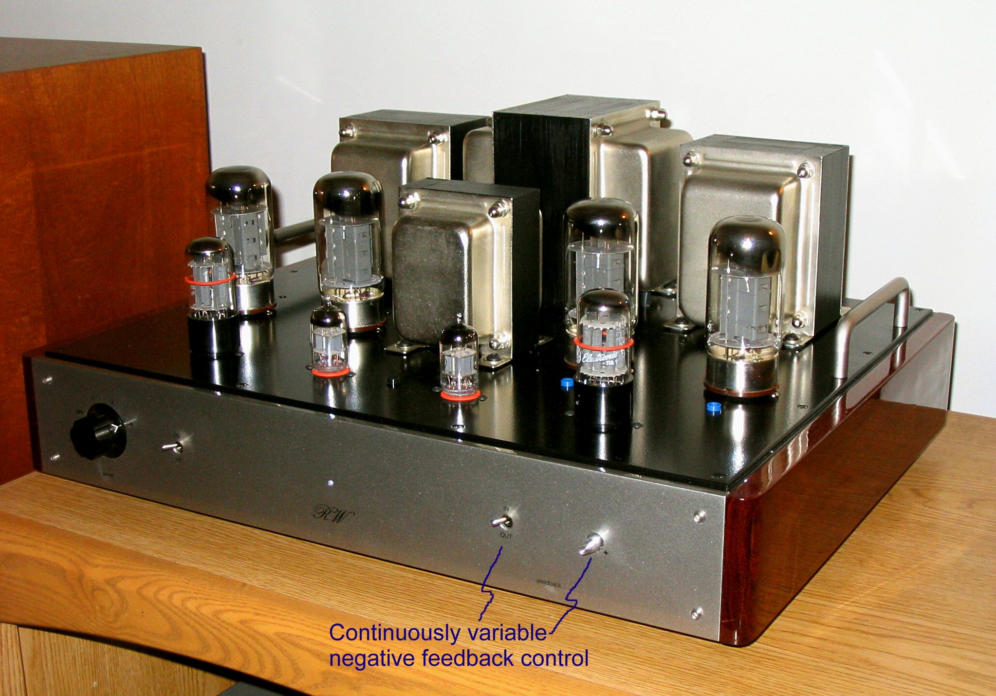
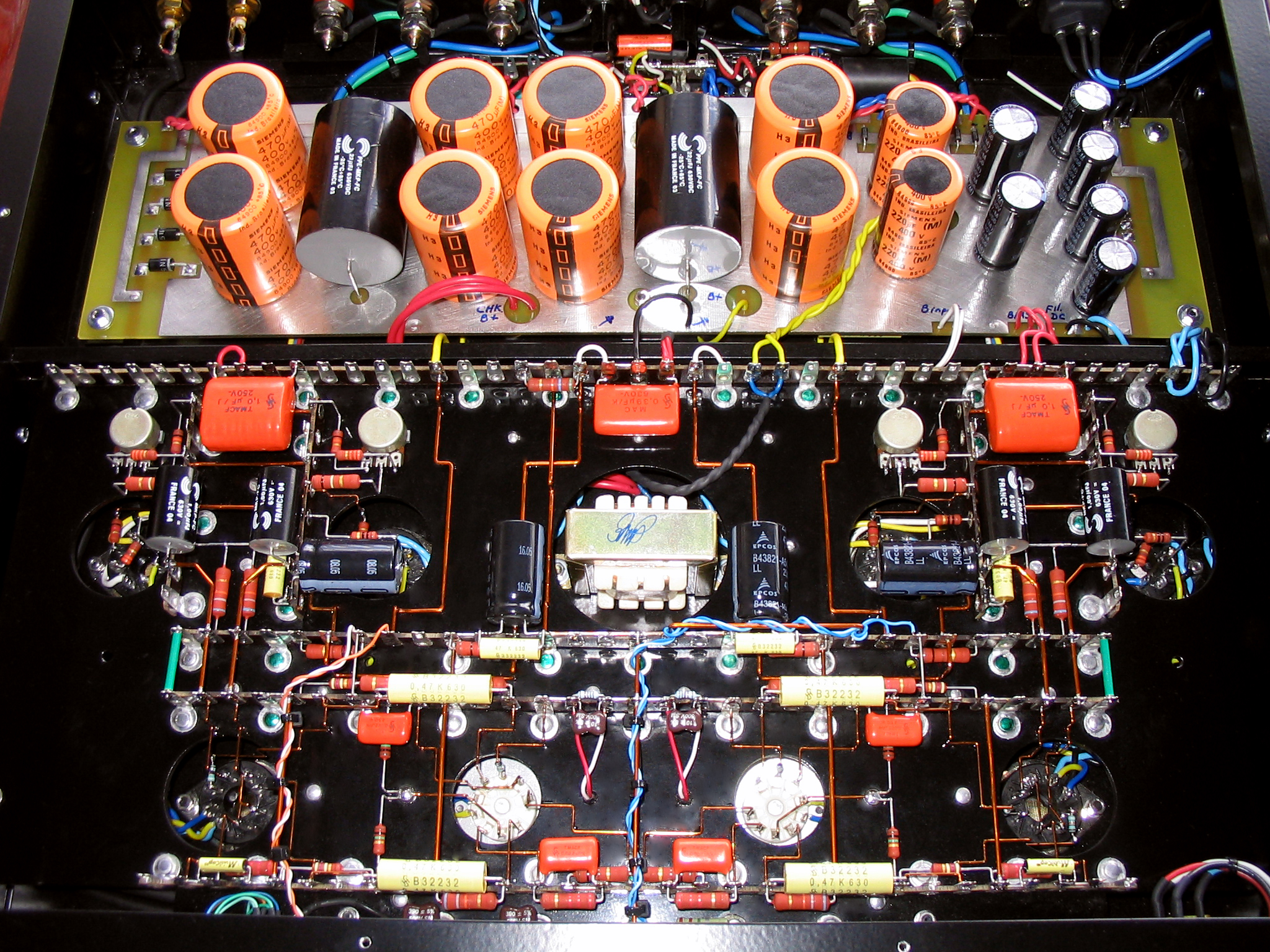
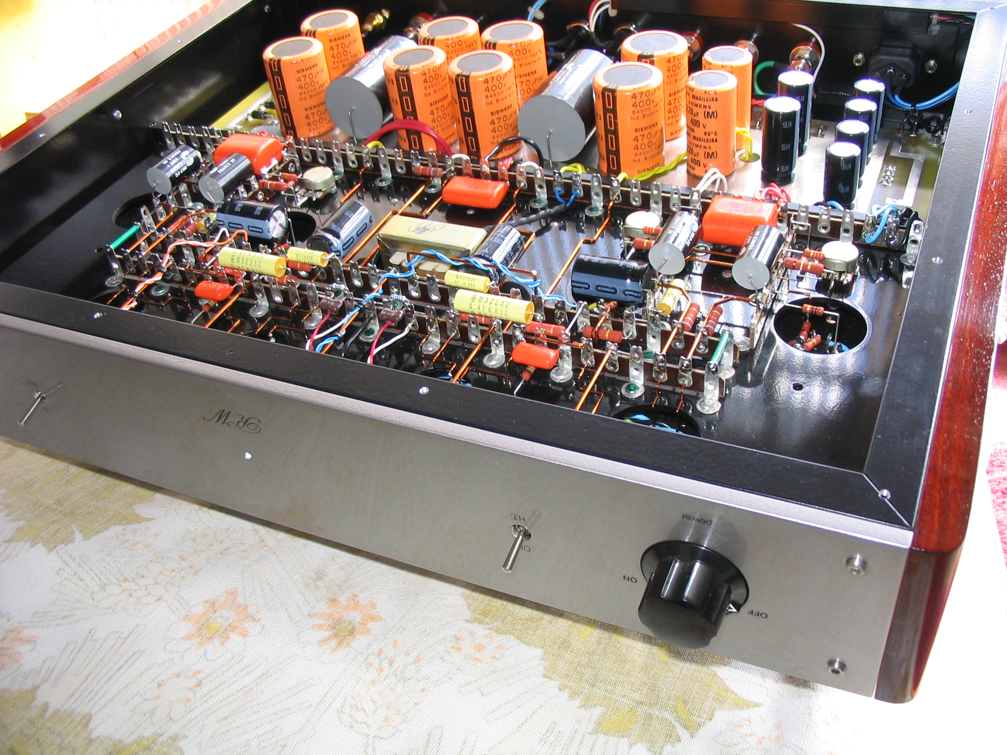
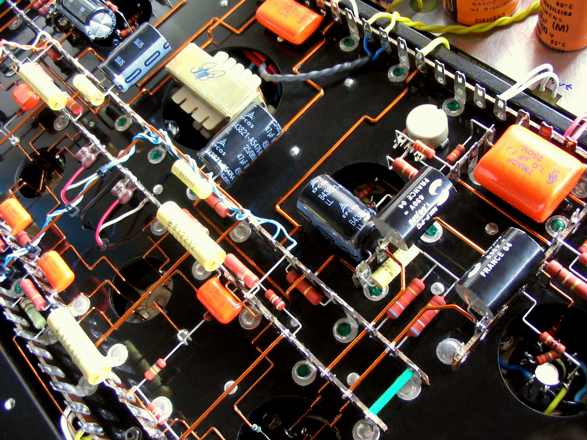
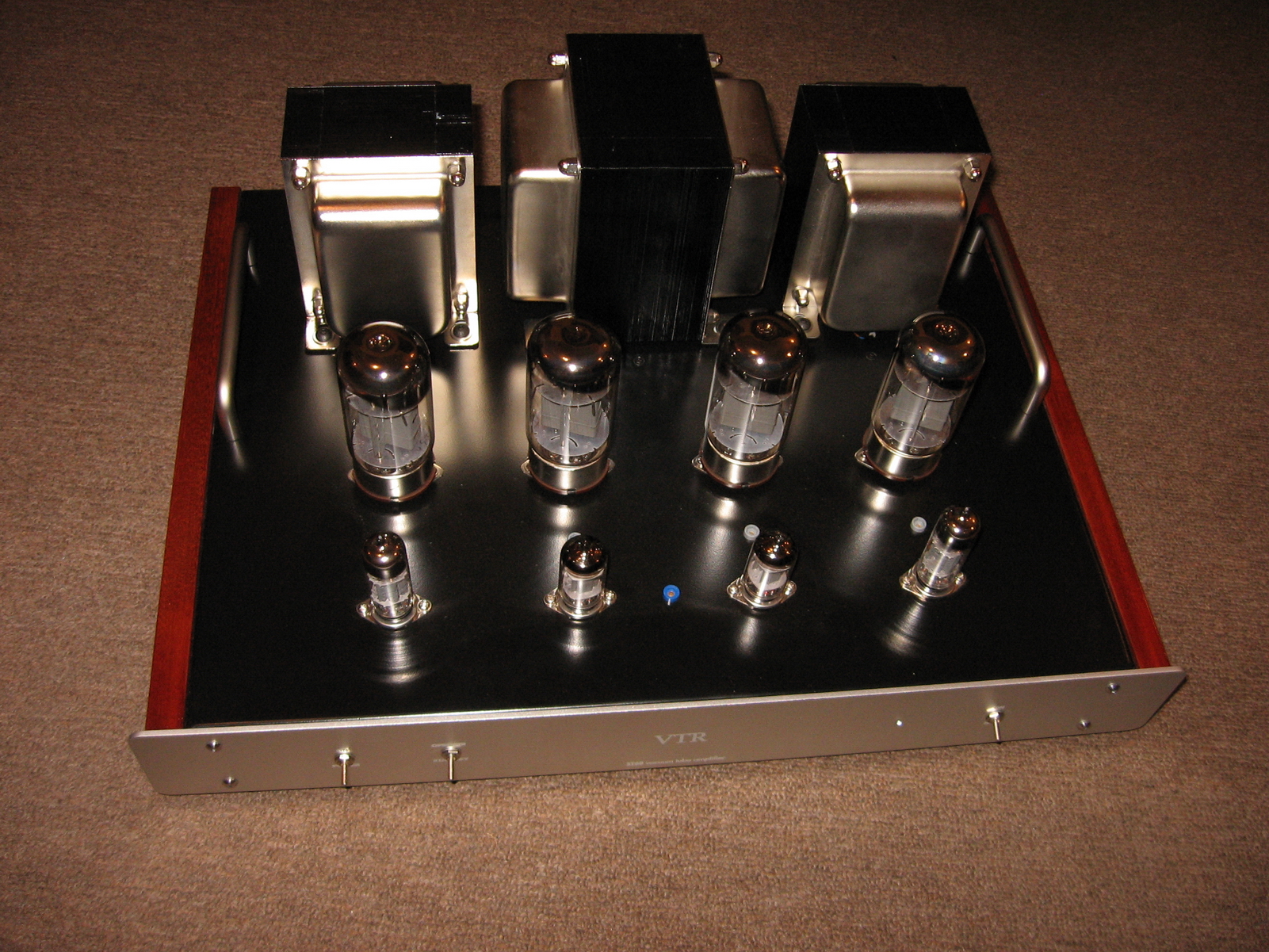
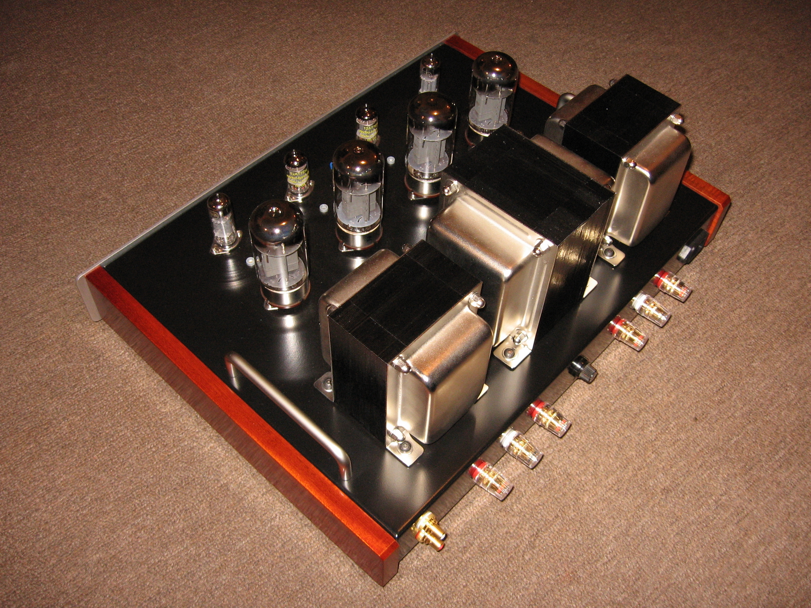
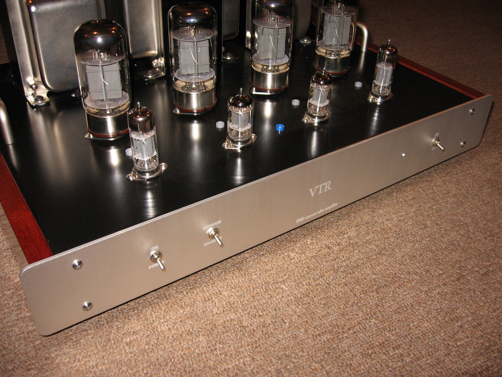
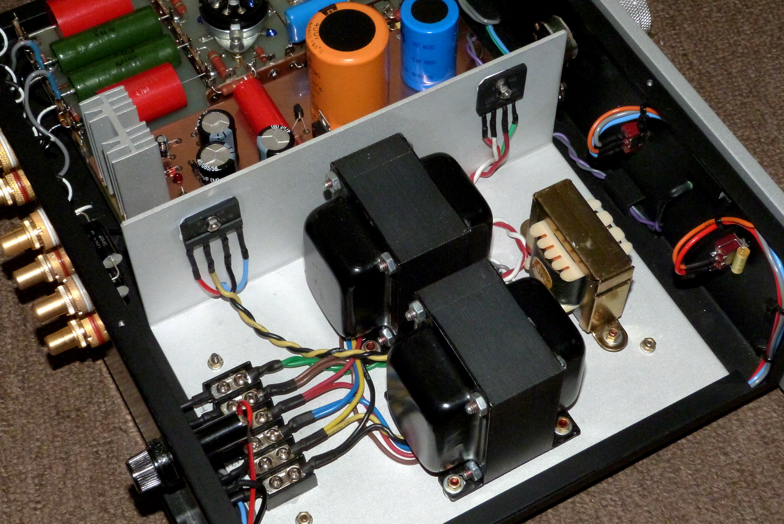
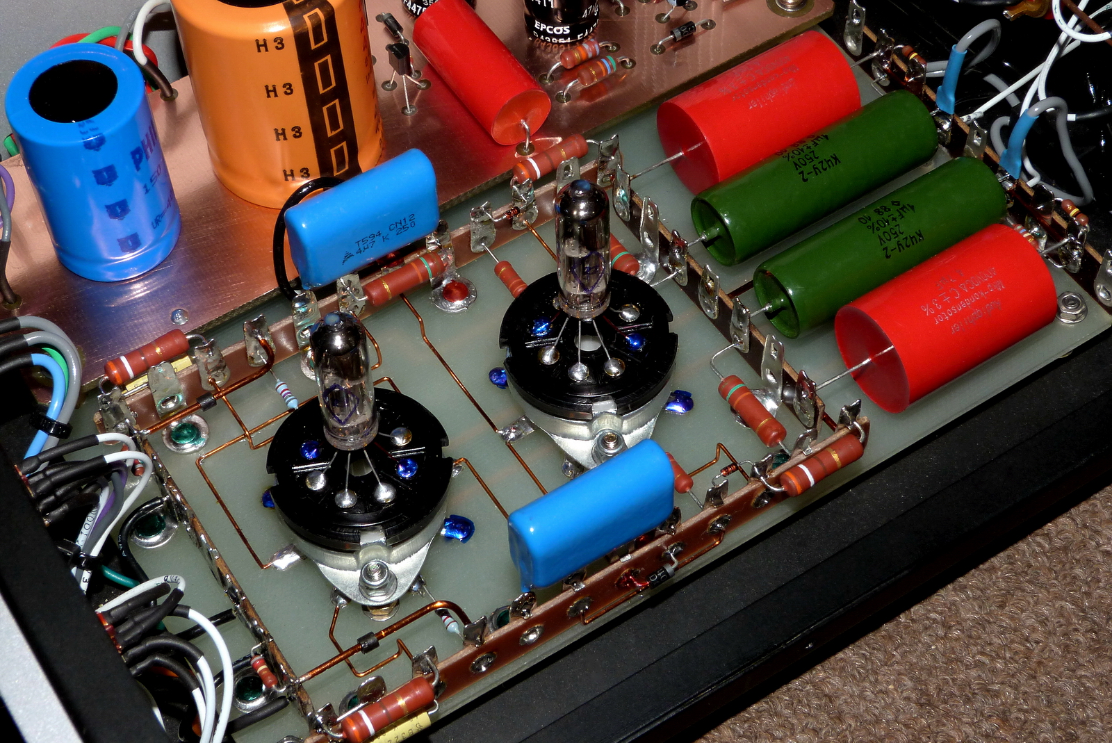
EXAMPLE 2: VTR POWER AMPLIFIERS
- Brazil
Central Brazil, Belo Horizonte City, Minas Gerais State
website:
email: rwellerson@hotmail.com


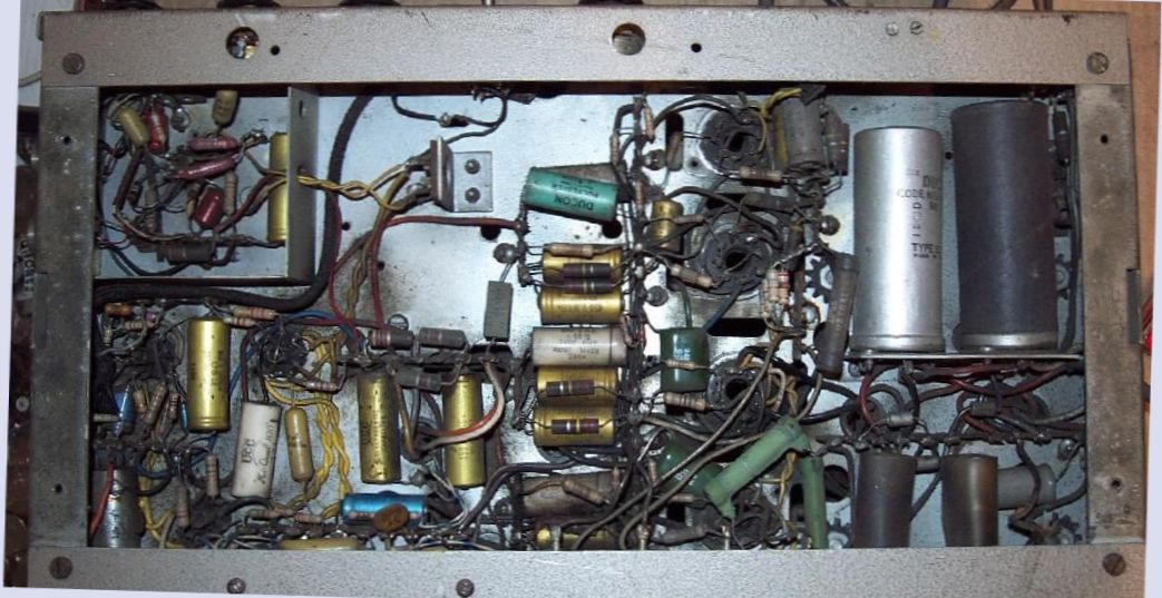
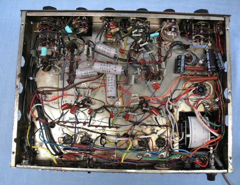
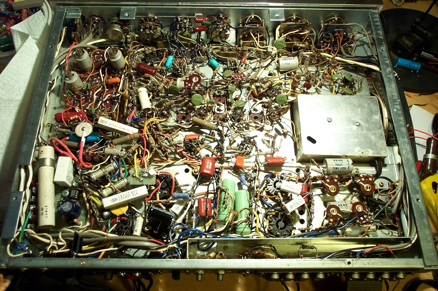
EXAMPLE 3: LAYOUTS TO AVOID
Note the psychedelic artform wiring and complex layouts.
Compare with the "CHASSIS AND
COMPONENT LAYOUT AND WIRING RULES" above
But they still work !!
Home
Page
This page is located at http://www.oestex.com/tubes/wiring.html
This page last modified 09 December 2015


